










Profile length variation shows up the same way on most lines. The stacker finishes a bundle of purlins, an operator pulls out a tape measure, and the fifth profile is 8 mm longer than the first. Every piece outside tolerance becomes scrap or site rework, and on a line running 12,000 parts a month the cost adds up fast.
Profile length variation is a length control problem, not usually a roll problem. The profile is formed correctly; the machine just cuts it at the wrong moment. This guide explains the 6 cutoff trigger accuracy improvement steps that hold length scatter inside ±1 mm, with root cause tables, tolerance data, and shop floor checks. For the full process background, see our всесторонний анализ технологии профилирующих станков.
What Is Profile Length Variation in Roll Forming?
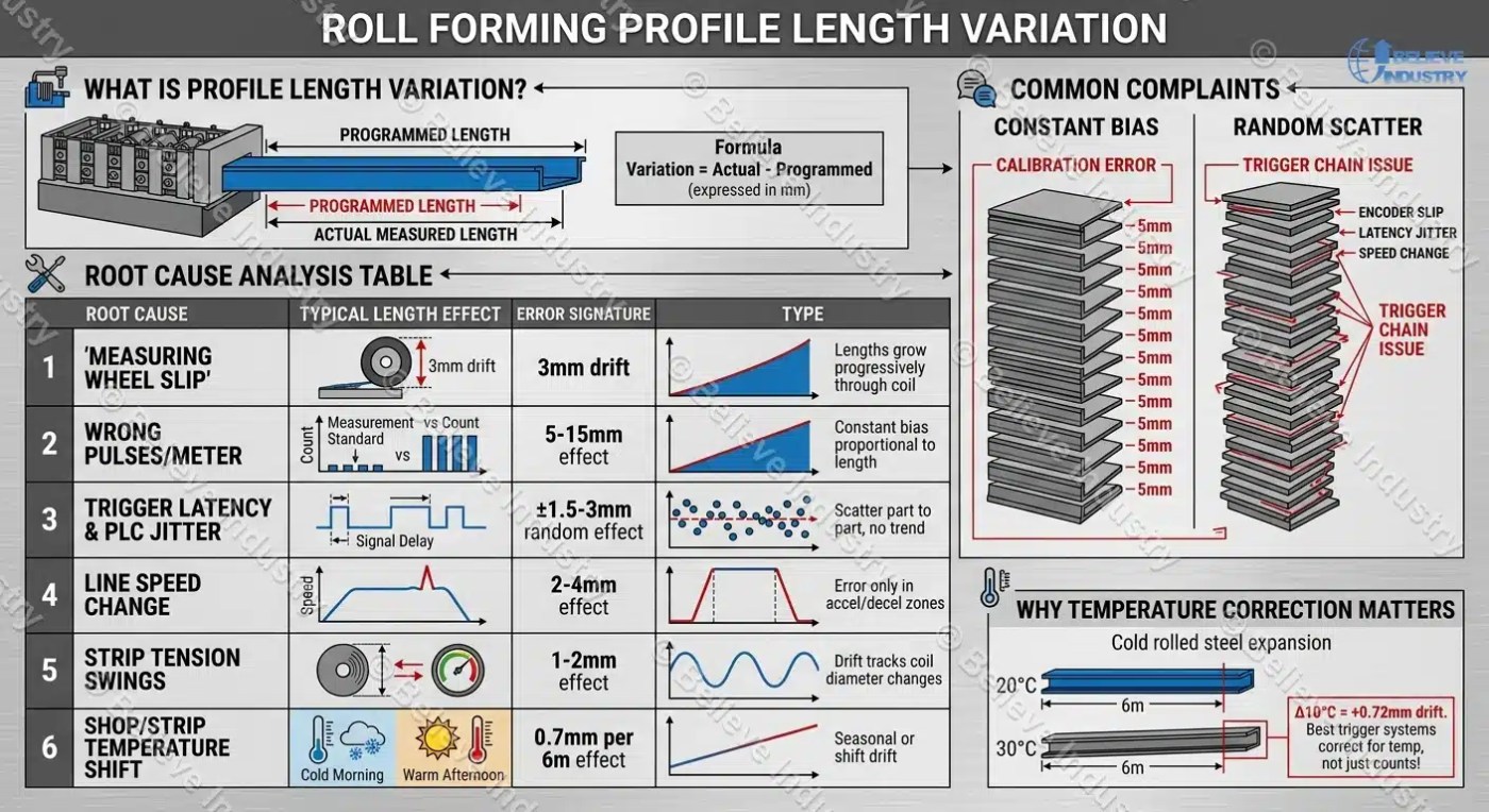
Profile length variation is the difference between the cut length programmed into the machine and the actual length measured on the finished profile, expressed in millimeters. It is the most common dimensional complaint from roll forming buyers, and it appears as either a constant bias or a random scatter.
A constant bias means every part runs long or short by a similar amount. The cause is usually calibration. Random scatter means parts swing around the nominal length, and the cause is usually in the trigger chain: encoder slip, latency jitter, or speed change.
The length is decided in the last few milliseconds of the cut cycle. Understanding where those millimeters come from is the first step, so the table below maps the typical sources.
| Root cause | Typical length effect | Error signature |
|---|---|---|
| Measuring wheel slip or worn tire | Up to 3 mm drift on a 6 m profile | Lengths grow progressively through the coil |
| Wrong pulses per meter setting | 5 to 15 mm on long parts | Constant bias proportional to length |
| Trigger latency and PLC scan jitter | ±1.5 to 3 mm random | Scatter part to part, no trend |
| Line speed change near the shear | 2 to 4 mm on one part | Error only in acceleration and deceleration zones |
| Strip tension swings from the uncoiler | 1 to 2 mm on a 6 m profile | Drift that tracks coil diameter changes |
| Shop or strip temperature shift | About 0.7 mm per 6 m per 10 °C | Seasonal or shift to shift drift |
| Shear backlash or blade holder wear | 0.5 to 1.5 mm | Offset appears after maintenance or tooling swaps |
Cold rolled steel expands about 0.012 mm per meter for every degree Celsius. A 10 °C swing between a cold morning start and a warm afternoon moves a 6 m profile by 0.72 mm before the shear even fires. That is why the best trigger systems correct for temperature, not just for encoder counts.
How the Cutoff Trigger Controls Cut Length
The cutoff trigger is the electrical signal that tells the shear to fire when the strip has reached the programmed length. On a modern roll forming line the signal comes from a rotary encoder, usually mounted on a measuring wheel that rides on the strip.
The measurement chain runs encoder to controller to shear. A сервопривод летающих ножниц closes that chain in about 1 ms, while a PLC (programmable logic controller) system with a conventional shear can take 10 to 50 ms from trigger to blade contact. The math is unforgiving: a 10 ms delay at a line speed of 20 m/min lets the strip travel 3.3 mm past the target point.
That delay is exactly why cutoff trigger accuracy matters more than shear force or blade sharpness. Cutoff is a secondary operation in the forming sequence, and like every secondary operation in the roll forming line it only adds value if it repeats exactly the same way on every part.
Step 1. Mount the Measuring Encoder So Slip Is Impossible
Encoder slip is the number one cause of progressive length error. If the measuring wheel skids or lifts off the strip, the encoder undercounts pulses and the line overruns the target, so every part comes out longer.
Mount the wheel on a clean, straight section of strip before the first forming stand, or on a flat zone of the finished profile. Apply spring pressure of 40 to 80 N, use a knurled or urethane coated wheel matched to the material, and keep the contact surface free of oil and scale.
Wheel diameter wear is the silent version of the same problem. A measuring wheel of 200 mm diameter loses 0.1 mm to polishing wear over a year, which shortens its circumference by about 0.3 mm per revolution. That adds up to roughly 0.5 mm of error per meter of profile, or 3 mm on a 6 m part. Calibrate the wheel against a traceable standard at least twice a year, using measurement services traceable to bodies such as the National Institute of Standards and Technology (NIST calibration services).
Step 2. Calibrate Pulses Per Meter on Real Production Strip
Pulses per meter is the number of encoder counts the controller expects per meter of strip travel. If that value is wrong, every part carries the same percentage error, and the longer the part, the bigger the miss.
Run a test length of at least 10 m, cut one part, and measure it with a calibrated steel tape. Divide the encoder pulses actually counted by the measured length to get the true pulses per meter, then enter that value in the controller.
Resolution is rarely the limit. A 2500 pulse per revolution encoder with quadrature counting on a 200 mm wheel resolves about 0.06 mm per count, far finer than the shear can hold. Recalibrate at every coil change, because strip thickness and surface finish change the effective rolling radius of the wheel.
Step 3. Compensate the Shear Lead Distance and Firing Point
A stationary shear stops the strip, clamps it, and cuts. A flying shear cuts on the move, which means the blade must fire before the target point so that the profile ends at the right place when the cut finishes.
The controller calculates the firing point from line speed, blade stroke time, and blade acceleration. On a servo flying shear the blade carriage is synchronized to the line encoder, so the controller fires at a computed position rather than a time delay, which is how these systems hold flying shear accuracy inside ±0.5 to 1.0 mm.
Check the shear every time the blade or blade holder is replaced. New blade geometry changes the stroke timing, and an uncompensated change of even 5 ms moves the cut by 1.7 mm at 20 m/min.
Step 4. Cut Trigger Latency and Scan Cycle Jitter
Latency is the fixed delay between the encoder pulse and the blade action. Jitter is the variation in that delay from part to part. Jitter is worse, because it shows up as random scatter that no offset can remove.
A PLC that scans every 10 to 20 ms adds up to 20 ms of variable delay. At 20 m/min that is up to 6.6 mm of scatter, which destroys any chance of holding ±1 mm. Route the encoder signal directly to the motion controller or servo drive, where update cycles run at 0.5 to 1 ms, and reserve the PLC for logic, not for length counting.
Never use a mechanical limit switch or proximity sensor as the primary length reference. These devices have switching repeatability of 0.1 to 0.5 mm at best and are only suitable for homing or end of stroke confirmation.
Step 5. Stabilize Strip Tension and Line Speed
Strip tension stretches steel elastically, and the stretch changes with coil diameter. A tension rise of 50 MPa stretches mild steel by about 0.25 mm per meter, so a tension swing between a full coil and a near empty coil can move a 6 m profile by more than 1 mm with no trigger error at all.
The payoff brake and разматыватель set that tension. Loose looping causes speed surges at the shear; over braking stretches the strip. Keep tension inside a defined band, and never cut during acceleration or deceleration unless the controller measures length from an encoder at the shear entry. Tension control also protects against related defects such as edge wave from strip tension instability.
Step 6. Add an Independent Inline Length Check and Close the Loop
Every calibration drifts eventually, so the line needs a second opinion. Measure the first three parts of every coil with a tape, plot the results, and act when the average or range moves past half the tolerance band.
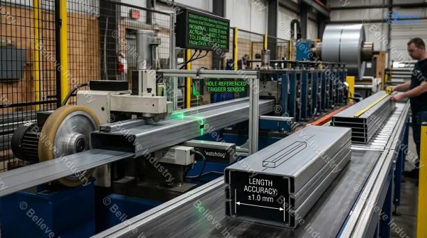
For high volume lines, add a second encoder or a laser length gauge after the shear as a watchdog. Modern controllers can apply a correction offset automatically when the watchdog and the main encoder disagree by more than a set value. Log every check: date, coil number, measured lengths, and the correction applied. That log turns a random complaint into a trend you can fix before the customer sees it.
When Profiles Are Pre-Punched: Cut From the Hole, Not the Encoder
Many purlin, floor deck, and rack upright profiles are punched before forming. On those parts the customer measures the distance from the last hole to the cut edge, not the overall length, so the cutoff must be referenced to the hole, not to an accumulated strip length.
An encoder trigger holds total length, but it cannot hold hole to end distance when the punch station drifts. Strip slip at the punch, die wear, or a shift between the punch station and the forming mill moves the hole pattern along the strip, and a length based cutoff repeats that error on every part.
Hole-referenced cutoff: a trigger method in which the shear fires at a fixed distance from a detected hole edge instead of from an accumulated length count. The hole becomes the zero reference for every part.
To add it to a pre-punch line, fit a micro laser distance sensor on a C frame or measuring bridge just ahead of the cutoff station, aimed at the strip surface. When the punched hole passes, the sensor detects the hole edge and signals the controller, which then counts the programmed number of encoder pulses from that edge to the shear firing point. Setup points:
- Choose a sensor with fast response and repeatability around ±0.05 mm, and mount it no more than 300 mm before the shear so strip sag cannot shift the reference.
- Set the detection threshold to ignore oil spots, scale, and surface marks. Confirm the trigger with a punched test part before production.
- For slots longer than about 50 mm, trigger on the trailing edge or use two sensors, because the strip moves while the slot passes.
- Log hole to end measurements with the same watchdog routine used for plain cut lengths.
Speed makes the sensor choice matter. At 20 m/min the strip travels 0.33 mm every millisecond, so a micro laser distance sensor with sub millisecond response keeps the hole edge reference inside ±1 mm even when the punch pattern drifts several millimeters upstream. Feed the sensor into the same motion controller as the encoder so the hole reference and the length count share one time base.
Cutoff Technology Comparison
Cutoff trigger accuracy depends on the shear type as much as on the trigger itself. The table below compares the three common cutoff technologies used in roll forming.
| Cutoff type | Typical length accuracy | Скорость линии | Примечания |
|---|---|---|---|
| Stationary hydraulic shear | ±0.5 to 1.0 mm | Batch, under 10 m/min | Strip stops for each cut; accurate but slow, no flying shear wear |
| Mechanical flying die | ±3 mm typical | 15 to 30 m/min | Cuts on the move; mechanical wear shifts timing over time |
| Сервоприводные летающие ножницы | ±0.5 to 1.0 mm | 20 to 40 m/min | Blade synchronized to line encoder; low maintenance, best trigger response |
The same accuracy hierarchy shows up in field reviews published by fabrication trade media such as Изготовитель. A servo flying shear holds the accuracy of a stationary shear at production speed, which is why it is the standard choice on purlin, floor deck, and high volume panel lines. Beli Rollforming has supplied servo flying shears on lines for over 15 years across more than 20 countries.

What Cut Length Tolerance Should You Specify?
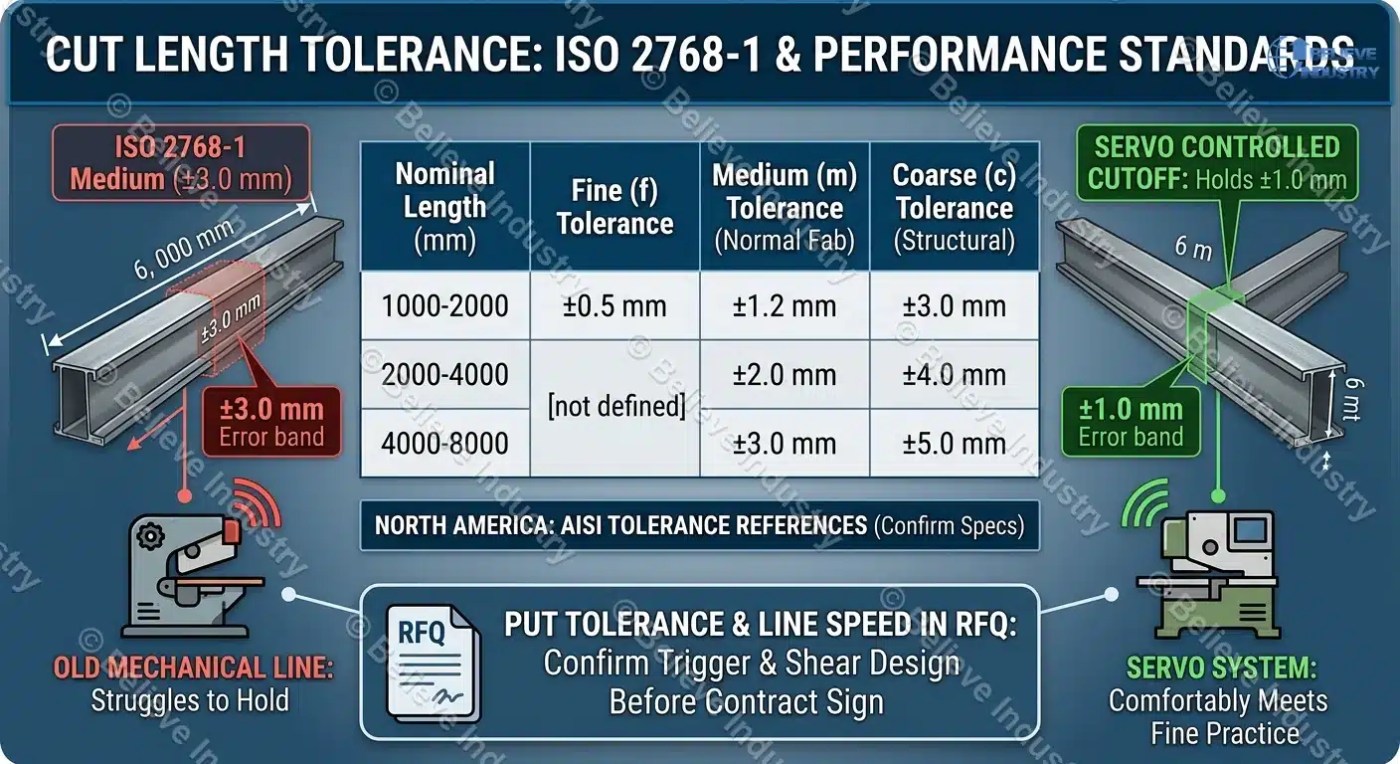
Buyers and builders often argue over cut length tolerance without a common reference. ISO 2768-1, published by the International Organization for Standardization (ИСО), defines general tolerances for linear dimensions and gives a practical baseline for cut length disputes. Class m (medium) covers normal fabrication work, class c (coarse) covers structural lengths.
| Nominal length (mm) | Fine (f) | Medium (m) | Coarse (c) |
|---|---|---|---|
| 1000 to 2000 | ±0,5 мм | ±1.2 mm | ±3.0 mm |
| 2000 to 4000 | not defined | ±2,0 мм | ±4.0 mm |
| 4000 to 8000 | not defined | ±3.0 mm | ±5.0 mm |
A 6 m purlin drawn to ISO 2768-1 medium class allows ±3.0 mm, which an old mechanical line struggles to hold. A servo controlled cutoff holds ±1.0 mm or better, so it comfortably meets fine practice for every length in the table. In North America, cold-formed steel framing tolerance references come from the American Iron and Steel Institute (AISI). Specify the tolerance on the drawing instead of leaving it general, and confirm the trigger and shear design can hold it before you sign the machine contract. Put the target tolerance and line speed in your roll forming machine RFQ so every supplier quotes against the same number.