


Good roll forming machine frame alignment puts every stand on one straight datum. Otherwise the strip leaves with a bow or a twist.
Twist is costly. A section can look correct and still rotate along its length. No exit gap tweak removes it, since the error is in the frame. Fixing roll forming machine frame alignment is geometry work before tooling work.
Here are five methods, a slab to strip sequence, and bands to verify in your shop. Every figure is a typical starting band, not a measured Beli result.
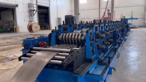
The machine that carries all of those stands is covered in the roll forming machine overview.
What Pushes a Frame Out of Line
Good roll forming machine frame alignment rarely fails at once. It drifts. Five root causes explain most drift: an uneven foundation, thermal growth, loose anchor bolts, worn shafts, and an uneven roll gap.
An uneven foundation sags the base rail. Survey the slab first.
Thermal growth is quiet. Steel grows about 12 micrometres per metre per degree Celsius, so a rise of 20 degrees adds close to 3 mm over a 12 m base.
Loose anchors let a stand rock by 0.10 mm under load. Torque to the bolt maker spec, often 150 to 250 Nm for M20 to M24 hardware.
Worn shafts wobble and make any roll forming machine frame alignment reading unstable. Replace them before you shim.
An uneven roll gap pulls the strip off centre. Set it to thickness plus 0.05 to 0.10 mm.
These causes argue for a fixed roll forming machine frame alignment order, from the slab upward.
Buckling in the strip often starts from the same load path that bends a frame, so check the seven root causes of profile buckling alongside the frame survey.
Residual stress after the last stand can mask a frame error, so read the springback in roll forming guide before you blame the rail.
Gap setting decides how clearly a shifted stand shows, so set it by the roll gap and material thickness rules first.
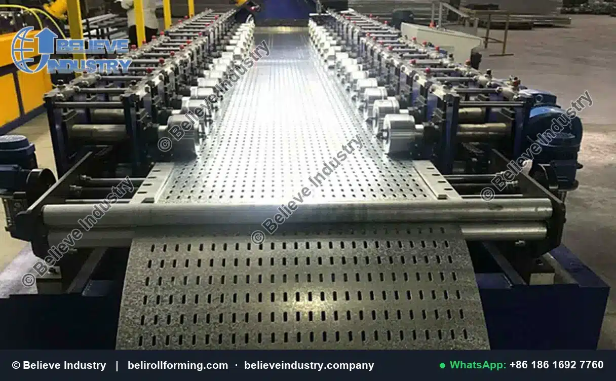
Cantilever stands make shaft end sweep easy to see and easy to correct.
The Alignment Sequence From Foundation to Running Strip
A repeatable roll forming machine frame alignment job follows a fixed order.
One, survey and repair the slab. Two, level the base rail with an optical level or laser tracker across 12 m. Three, torque anchors from the centre outward.
Four, seat stands with a straightedge and shim packs. Five, stretch a taut wire along the line centre as one shared datum. Six, sweep each shaft end with a dial indicator.
Seven, set roll gap to thickness plus 0.05 to 0.10 mm. Eight, soak to a stable temperature and recheck the rail. Nine, run a 6 m strip and measure bow and twist. Ten, freeze the shims, torque values and gap sheet as the baseline.
A documented roll forming machine frame alignment sequence keeps two technicians on the same datum.
Alignment fits inside the wider handover routine covered by roll forming machine commissioning.
Welded base frames follow a published sheet steel welding code, and the AWS welding standards define that practice.
Five Precision Methods That Stop Twist
Each method answers a different question about roll forming machine frame alignment, so use all five in order. Together they define what roll forming machine frame alignment means on a real line.
Bands below are typical starting values, not measured Beli results. Confirm each in your shop.
Method 1: Laser tracker or optical level on the base rail
Mount the instrument beyond the line, fit one plane to a 1 m point grid, and shim low feet. Typical band: 0.05 to 0.15 mm per metre, with 0.10 to 0.20 mm over 12 m for an optical level.
Method 2: Taut wire with feeler gauge datum
Clamp a 0.3 to 0.5 mm wire at both ends under known tension and measure to a boss on each stand with a feeler gauge. Correct sag from tension and span. Typical band: 0.10 to 0.30 mm over 6 to 12 m.
Method 3: Dial indicator sweep on shaft ends
Rotate each shaft one full turn against a dial indicator on a magnetic base and read total indicator runout. Typical band: 0.02 to 0.05 mm at each end and 0.05 to 0.10 mm along the body. This separates a level frame from true roll forming machine frame alignment.
Method 4: Straightedge plus shim pack under stands
Lay a ground straightedge across two stand bases and probe gaps with a feeler gauge, then add 0.05 mm shim steps under the low foot. Typical band: a residual gap of 0.05 to 0.15 mm with full bearing.
Method 5: Running strip test measured for bow and twist over 6 m
Run a 6 m strip at 10 to 30 m/min, lay it on a flat table, and measure side bow and corner lift. Typical band: bow of 1 to 3 mm and twist of 1 to 2 degrees over 6 m. This reads roll forming machine frame alignment as the product sees it.
| Method | Checks | Typical accuracy band | Stage | Cost |
|---|---|---|---|---|
| Laser tracker or optical level | Rail flatness | 0.05 to 0.15 mm per metre | Base set | High |
| Taut wire with feeler gauge | Line datum | 0.10 to 0.30 mm over 6 to 12 m | Rough set | Low |
| Dial indicator sweep | Shaft runout | 0.02 to 0.05 mm TIR | Stand check | Low |
| Straightedge plus shim pack | Foot contact | 0.05 to 0.15 mm gap | Leveling | Low |
| Running strip test over 6 m | Bow and twist | 1 to 3 mm, 1 to 2 degrees | Acceptance | Medium |
The laser tracker belongs at the start and the strip test last. A sound roll forming machine frame alignment programme uses cheap methods often and the expensive one at handover.
The rolls themselves define the reference that all of this protects, as the roll forming tooling guide explains.
Material grade changes how much twist the strip will tolerate, so check the grade against SAE material and process standards.
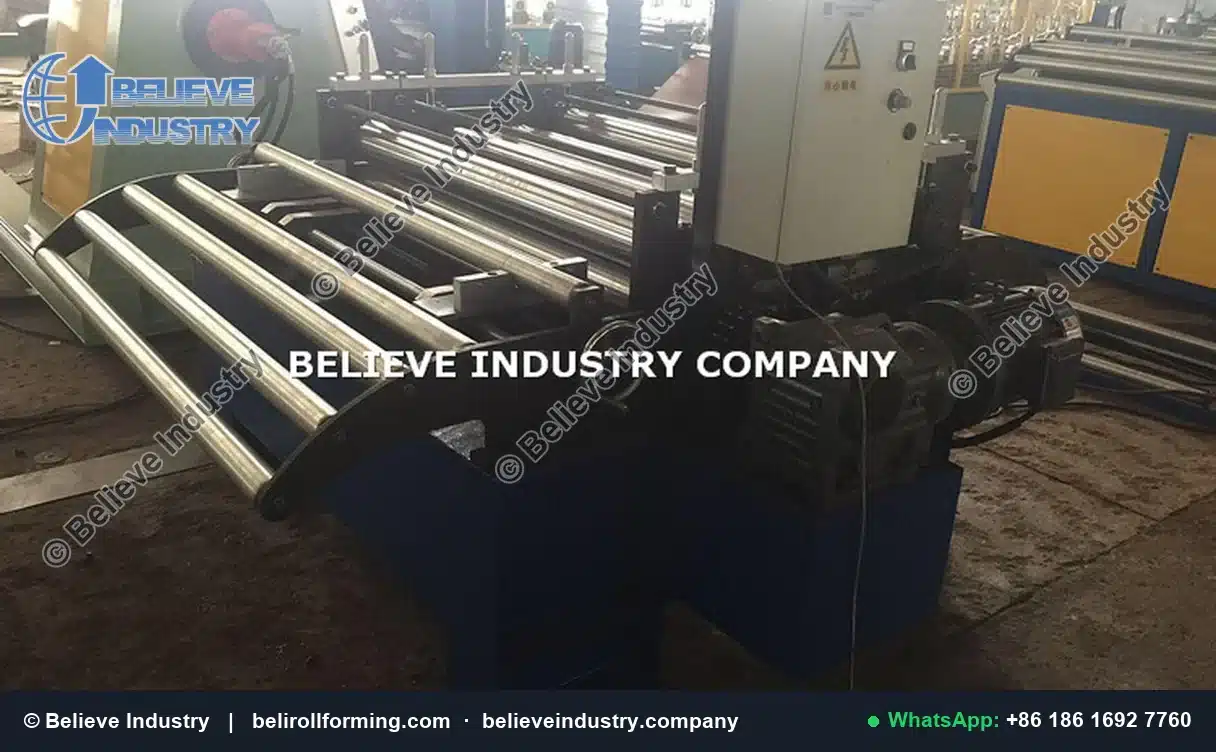
A leveling device shows how uneven roll gap turns into bow and twist.
Reading Faults From Strip Symptoms
A symptom table turns a vague complaint into a short check list. Good roll forming machine frame alignment diagnosis changes one variable and re-runs the 6 m strip.
| Symptom | Likely fault | Confirm with | First fix |
|---|---|---|---|
| Steady bow over 6 m | Rail off level | Laser tracker | Reshim low foot |
| Repeating bow | Loose anchor or worn shaft | Dial indicator | Retorque, inspect shaft |
| Twist toward exit | Uneven roll gap | Feeler gauge | Reset gap |
| Bow after warm-up | Thermal growth | Rail recheck | Soak and reset |
| One corner lifts | Stand height mismatch | Taut wire | Rebuild shims |
Use the table as a map, not a verdict. The strip test closes every roll forming machine frame alignment change.
A shifted stand can mark the surface as well as bend the section, which is what surface scratch defects often point back to.
A written record turns a visual guess into a repeatable check, which is the core of a roll forming inspection.
High strength grades make small alignment errors far more visible, a point the AHSS Insights forming guidelines cover in detail.
Acceptance Bands and Shop Verification
Every tolerance here is a typical starting band, not a measured Beli result. Treat each as a starting point for roll forming machine frame alignment on your own floor.
Six numbers anchor the method: rail flatness 0.05 to 0.15 mm per metre, shaft runout 0.02 to 0.05 mm, stand gap 0.05 to 0.15 mm, wire spread 0.10 to 0.30 mm, strip bow 1 to 3 mm over 6 m, and twist 1 to 2 degrees over 6 m. These are the numeric core of roll forming machine frame alignment on most lines.
Five designations frame the paperwork: ISO 9001 for calibration records, AWS D1.3 for base frame welds, AISI S100-16 for cold formed steel design, EN 10162 for delivery conditions, and EN 1993-1-3 for member design. Quote the edition on the setting sheet.
Note the instrument serial beside each value, and when a band disagrees with the strip, trust the strip. The point of roll forming machine frame alignment is repeatable product, not a textbook number.
Industry groups publish the flatness language used in handover documents, including the Metal Construction Association technical resources.
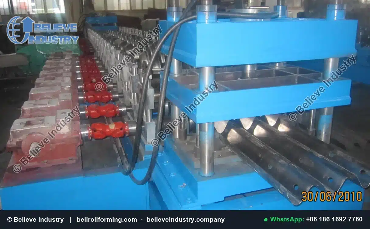
Guide poles hold the stand in line after the shim pack is set.
Holding Alignment After Commissioning
A line that leaves straight will still move. Schedule a short roll forming machine frame alignment audit after month one, a foundation repair, a tooling change, or drive service.
Read the wire datum, sweep two shaft ends, run one 6 m strip, and compare with the baseline. Log the date, stand number, shim thickness, torque, and bow and twist.
Stable roll forming machine frame alignment is a maintenance habit, not a one time setup.
Frequently Asked Questions
1. What is roll forming machine frame alignment? It is setting the base rail, stands and shafts on one straight datum so the strip exits flat.
2. How often should the frame be realigned? Recheck roll forming machine frame alignment after the first production month and at fixed intervals after that.
3. Which method is the most accurate? A laser tracker or optical level on the base rail, at about 0.05 to 0.15 mm per metre.
4. Can a taut wire replace a laser tracker? No. A taut wire gives a centre line at 0.10 to 0.30 mm, but it does not measure rail level.
5. What does a dial indicator sweep prove? It proves each shaft end runs true, at 0.02 to 0.05 mm total indicator reading.
6. How long a strip should the running test use? Use 6 m and measure bow and twist over that full length, since a shorter piece hides drift.
7. Are the tolerance figures Beli measured results? No. Every band is a typical starting value that needs shop verification on your own line.
8. Does springback affect roll forming machine frame alignment readings? It does not change frame geometry, but it can hide a frame error, so measure the strip itself.
Conclusion
Roll forming machine frame alignment is a geometry problem before a tooling problem. Level the base, seat the stands, true the shafts, set the gap, and confirm with a 6 m strip.
Record the shim packs, torque values, bow and twist, and hold that baseline with recurring audits. Consistent roll forming machine frame alignment shows as flat product, not a perfect number.
Beli Rollforming has built roll forming machines since 2005. We have delivered 500+ machines to 50+ countries from a 15,000 m² plant, with 80+ engineers and technicians. Every machine carries a 24-month warranty on the complete machine. Send us your profile drawing and coil grade, and we will tell you the alignment bands the line can hold.
Last updated: 2026-11-11
Article Changelog
- 2026-11-11: First publication. Five precision methods, a foundation to running strip sequence, a method comparison table, a fault-to-symptom table, and eight FAQ entries.
Next Review Triggers
- A revision to AISI S100-16, EN 10162 or EN 1993-1-3 that changes tolerance criteria
- New shop verification data outside the 0.6 to 3.0 mm coil band
- A customer line with a base rail longer than 12 m
- A change to the AWS D1.3 welding requirements for base frames


 English