


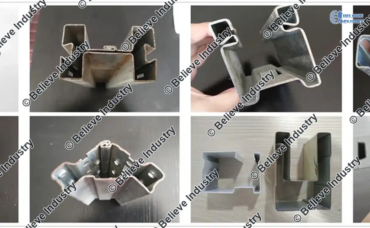
Accurate roll forming profile measurement confirms a formed section matches its drawing. It covers web depth, flange width, bend angle, inside radius and cut length. A 0.4 to 3.0 mm coil can drift by tenths of a millimetre.
This guide compares seven methods for roll forming profile measurement with a table of accuracy, cycle time, cost band and best use. It also covers coil sampling, springback, temperature, and a moving line versus a cut sample. Confirm figures in your shop.
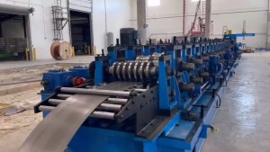
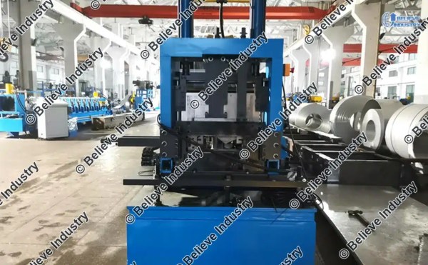
The machines that produce these sections are described on one page.
What Roll Forming Profile Measurement Has to Capture
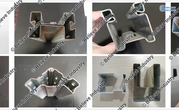
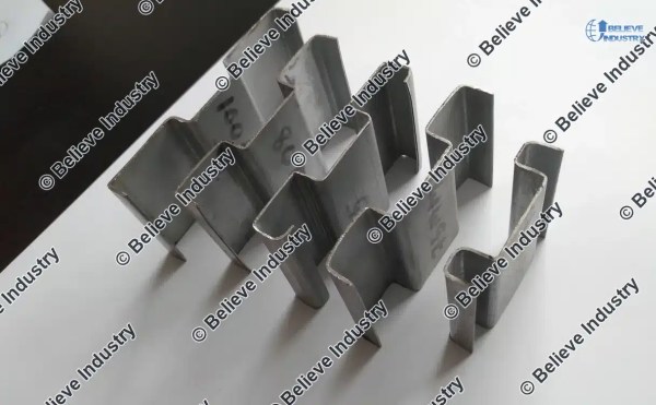
Roll forming profile measurement starts with the drawing. A cold formed section carries five or six critical dimensions set by the drawing, the roll tooling and the cutoff trigger.
Tolerances are not universal. A steel deck profile to SDI criteria may allow a width band near 1.5 mm on a 300 mm section, while a trim to EN 10162 can be tighter. Both need a written callout. roll forming profile measurement is only as good as its datum, so pick one face and one edge and measure from them every time. Match the instrument to the band: 0.20 mm does not need a 0.005 mm machine.
The rolls that shape each corner set the dimensions an instrument reads.
See roll forming tooling basics
Industry groups publish technical notes on cold formed steel tolerances.
Metal Construction Association technical resources
Roll gap relative to strip thickness moves the finished dimensions.
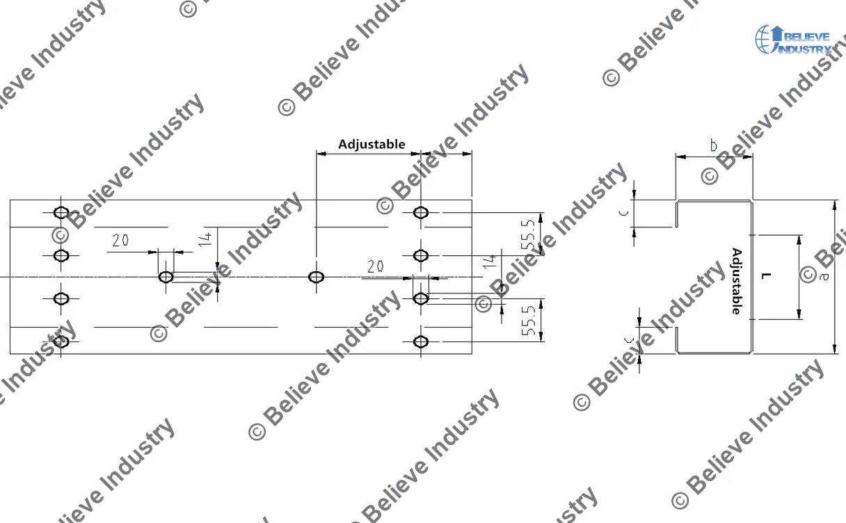
The drawing sets the nominal values that roll forming profile measurement checks against.
Seven Methods Compared: Accuracy, Cycle Time, Cost and Best Use
Seven tools cover most roll forming profile measurement work: three non contact optical tools and four contact tools. The table compares accuracy, cycle time, cost band and best use for each roll forming profile measurement method.
| Method | Typical accuracy | Cycle time | Cost band | Best use |
|---|---|---|---|---|
| Laser profile scanner, bench or handheld | 0.02 to 0.05 mm | 2 to 10 s per section | High | Full section shape, first article and lab checks |
| Optical comparator, also called a shadowgraph | 0.02 to 0.05 mm | 1 to 3 min per setup | Medium | Bend angle, inside radius, small profiles |
| Coordinate measuring machine (CMM) | 0.005 to 0.02 mm | 5 to 20 min per part | High | Complex sections, hole position, datum reports |
| Digital caliper | 0.02 to 0.05 mm | 5 to 15 s per dimension | Low | Flange width, web depth, thickness on the floor |
| Radius gauge | 0.1 to 0.25 mm | 5 to 10 s per corner | Low | Inside radius and quick corner checks |
| Go/no-go fixture | Pass or fail only | 1 to 3 s per part | Low to medium | Production screening of one critical dimension |
| Line-mounted laser or vision gauge | 0.05 to 0.2 mm | Continuous, real time | High | 100 percent inspection on a moving line |
No single roll forming profile measurement tool wins on every axis. A coordinate measuring machine is most accurate but takes 20 minutes per part. A go/no-go fixture gives no number yet screens a part in 2 seconds.
A laser profile scanner and an optical comparator both read a full 2D section. The scanner is faster, while the comparator, often called a shadowgraph, needs a clean cut edge. The line-mounted laser or vision gauge reads a moving strip. A roll forming profile measurement plan pairs one fast screening tool with one accurate reference tool.
Measuring the inside radius has its own grade rules.
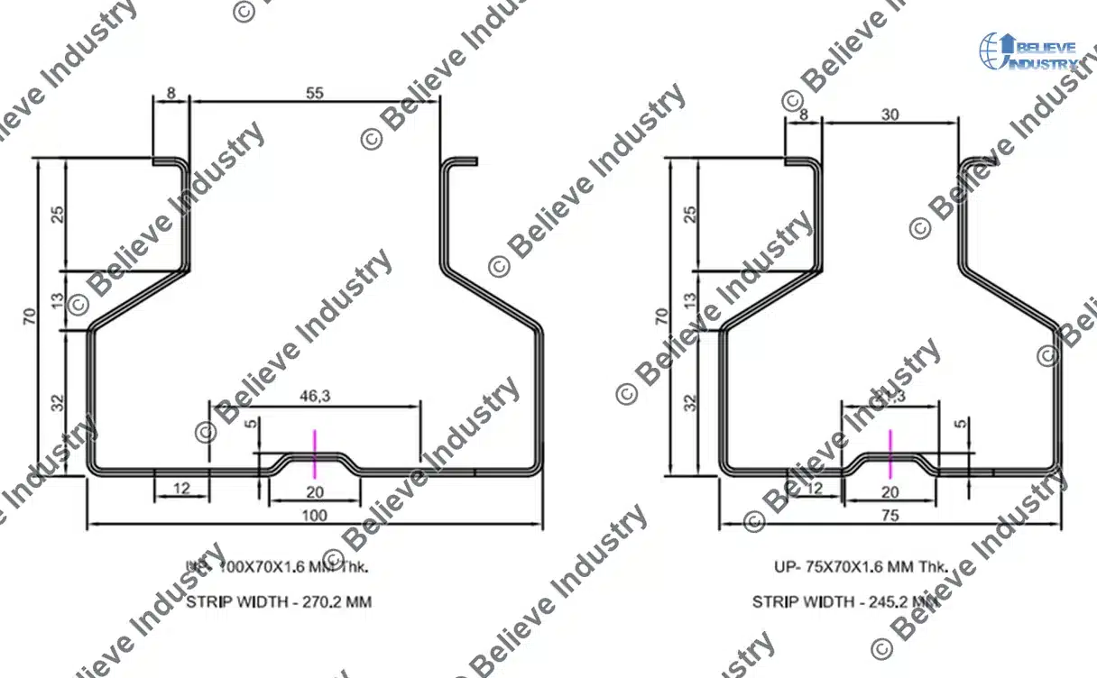
A section drawing fixes the datums before any gauge is chosen.
Where to Sample: Start, Middle and End of the Coil
A coil is not uniform end to end. The head carries the setup transient, the tail carries coil crown and changing tension, and steady state sits in the middle.
Take roll forming profile measurement samples at the start, middle and end of every coil. Keep three parts from the head and three from the tail, and log the metre mark on each. roll forming profile measurement on the middle sample shows capability. roll forming profile measurement on the head and tail shows drift. Compare the three before you move a stand. A common plan takes 2 parts per 1000 m of steady run.
A wider inspection plan covers coating and hole position too.
Springback, Temperature, and a Moving Line Versus a Cut Sample
A 90 degree corner does not stay at 90 degrees. Mild steel springs back 1 to 3 degrees and HSLA grades 3 to 6 degrees, so the last stand overbends. That is why roll forming profile measurement belongs on the finished part, not at the last stand.
Springback is a material effect with its own design rules.
Read the springback in roll forming guide
Temperature is a hidden term in every roll forming profile measurement. Steel grows about 0.012 mm per metre per degree Celsius and aluminium near 0.023 mm. Hot parts can read 0.05 to 0.10 mm long on a 1 metre web. Let the sample reach 20 degrees Celsius before you log roll forming profile measurement data.
Aluminium section data is published by alloy and temper, not by gauge.
Aluminum Association design data
A line-mounted laser or vision gauge reads a still moving strip. It gives 100 percent coverage, but it cannot see springback after the cutoff. A cut sample sits free on a bench and shows the relaxed final shape. Contact tools need a stopped cut sample. Set a correlation offset between roll forming profile measurement on the line and roll forming profile measurement on the bench.
Cut length on a moving line depends on the trigger and encoder.
Read about profile length variation and cutoff trigger accuracy
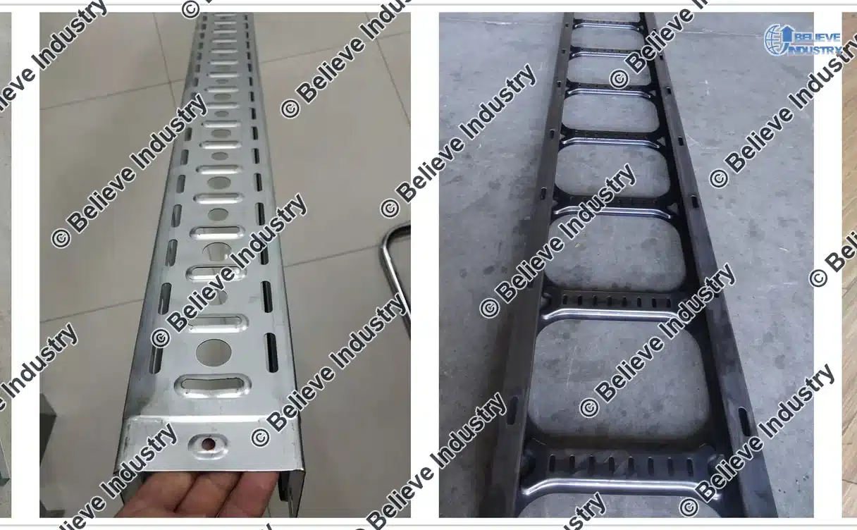
Hole position and section size are recorded together on the first article.
A Measurement Uncertainty Budget With Concrete Numbers
A roll forming profile measurement budget lists each error source in millimetres. These are typical starting values for a 1 metre section at 20 degrees Celsius, not measured results from any shop.
| Uncertainty source | Typical value (mm) | How to reduce it |
|---|---|---|
| Instrument calibration | 0.02 | Use a current calibration certificate |
| Readout resolution | 0.01 | Choose a finer scale instrument |
| Thermal drift, 1 m steel, 5 C | 0.06 | Hold 20 C and let the part soak |
| Operator repeatability | 0.03 | Use a fixed datum and a trained operator |
| Fixture and datum error | 0.04 | Machine a hard stop and clean the faces |
| Springback relaxation after cut | 0.05 | Wait 10 min and re-read the angle |
| Combined standard uncertainty, root sum of squares | 0.10 | Add the squares then take the root |
| Expanded uncertainty, k = 2 | 0.20 | Double the combined value for reporting |
Adding the six sources as a root sum of squares gives 0.10 mm, and doubling for a coverage factor of 2 gives 0.20 mm. The thermal term dominates: a 5 degree rise on a 1 metre web adds 0.06 mm. Build a written uncertainty budget before you agree a tight roll forming profile measurement band, and use it to judge if a tool is fit for a given roll forming profile measurement.
The tolerance band itself comes from the standard on the drawing.
SDI and EN Tolerance Callouts, and a Sign-Off Plan
Put the tolerance standard on the drawing before roll forming profile measurement begins. SDI criteria cover steel deck, EN 10162 sets delivery conditions, EN 1993-1-3 covers member design, and AISI S100-16 covers North American design. Quote the edition. A callout such as 1.5 mm on a 300 mm section is a starting band, not a universal limit. A quality system such as ISO 9001 keeps the records together.
A sign-off plan fixes how roll forming profile measurement is recorded. Name the instrument, datum, sample count and acceptance band, then freeze the recipe.
Sheet metal and duct work follow their own published tolerances.
AWS D1.3 gives the acceptance criteria for welded sheet steel assemblies.
Frequently Asked Questions
1. What is roll forming profile measurement? It is the set of checks confirming a formed section matches its drawing, covering web depth, flange width, bend angle, inside radius and cut length.
2. Which tool is most accurate for roll forming profile measurement? A coordinate measuring machine is most accurate at 0.005 to 0.02 mm, but it takes 5 to 20 minutes per part.
3. How many samples should I take from a coil? Take three parts at the coil start and three at the end, plus two parts per 1000 m of steady run.
4. Why do inline readings differ from a cut sample? An inline laser reads a moving constrained strip while a cut sample shows the relaxed shape after springback, so the two need a correlation offset.
5. Does temperature affect roll forming profile measurement? Yes, steel grows about 0.012 mm per metre per degree Celsius, so a 5 degree rise adds 0.06 mm on a 1 metre web.
6. How does springback change the measurement? Springback opens a 90 degree corner by 1 to 3 degrees in mild steel and 3 to 6 degrees in HSLA, so measure the finished part.
7. What is a measurement uncertainty budget? It is a list of error sources, such as calibration, resolution, temperature and repeatability, combined as a root sum of squares.
8. Which standards set roll forming tolerances? SDI covers steel deck, EN 10162 sets delivery conditions, EN 1993-1-3 covers member design, and AISI S100-16 covers North American design.
9. When should I use a go/no-go fixture? Use a go/no-go fixture for fast screening of one critical dimension when a pass or fail answer is enough and no number is needed.
Conclusion
roll forming profile measurement is a system, not one instrument. The seven methods trade speed against accuracy and cost, so pick one reference tool, one screening tool, and a written sampling plan.
Sample the start, middle and end of the coil. Let parts reach 20 degrees Celsius and measure springback on the finished part. Set a correlation offset between a line reading and a cut sample reading, and build a written uncertainty budget before you agree a tight roll forming profile measurement band.
Confirm every starting value in your own shop. SDI, EN 10162 and AISI S100-16 give the frame for roll forming profile measurement, but your drawing sets the limit.
Beli Rollforming has built roll forming machines since 2005. We have delivered 500+ machines to 50+ countries from a 15,000 m² plant, with 80+ engineers and technicians. Every machine carries a 24-month warranty on the complete machine.
Last updated: 2026-11-14
Article Changelog
- 2026-11-14: First publication. A seven method comparison table, a coil sampling plan, springback and temperature notes, an uncertainty budget table, and nine FAQ entries.
Next Review Triggers
- A revision to SDI criteria, EN 10162 or AISI S100-16 that changes section tolerances
- New calibration data for a laser or vision gauge outside the 0.02 to 0.20 mm band
- A customer drawing that calls for a tolerance tighter than 0.05 mm
- A line speed change that breaks the correlation offset

 English