


Cellular floor deck roll forming runs two coil lines into one weld station. A formed deck leaves the main train, a flat pan leaves a second train, and both are welded into closed cells before the cut-off. The forming stands decide the profile. Coil width, speed matching, and weld pitch decide the output.
Beli Rollforming builds roll forming machines and has over 15 years of tooling work in 20+ countries. The six techniques below come from deck line commissioning, not from a catalogue.
The cells carry conduit, cable, and sprinkler runs, and the pan works as a bottom flange. A pan that wanders 2 mm off the rib centre line still looks fine in a bundle. It fails at the weld.
1. Two Coils Set the Whole Line
Cellular production starts with developed strip width, not with tonnage. The deck coil must yield the rib geometry, the side laps, and the embossments. The pan coil must match the finished coverage minus the lap. The gauge pair is written as deck over pan.
| Item | Typical range | What it controls |
|---|---|---|
| Deck depth | 1.5 / 2.0 / 3.0 in (38 / 51 / 76 mm) | Cell height, span, slab depth |
| Coverage width | 24 or 36 in (610 or 914 mm) | Coil width and pan width |
| Rib pitch | 6 to 12 in | Cell width, service routing |
| Deck gauge | 22 to 16 (0.76 to 1.52 mm) | Rib stiffness, weld balance |
| Pan gauge | 24 to 20 (0.60 to 0.91 mm) | Cell stiffness, burn-through risk |
| Common pairs | 20/20, 18/20, 18/18, 16/18, 16/16 | Weld schedule and tooling set |
Coating matters as much as thickness. Most deck runs G90 galvanized to ASTM A653, and the zinc layer is what the electrode sees first. A quiet switch from G60 to G90 shows up as weld spatter within a week.
The floor deck machine buying guide covers coil handling. For cellular work add one check: both uncoilers must take the same coil ID, and the pan mandrel must be rated for the lighter coil.
2. Split the Forming Train, Not the Frame
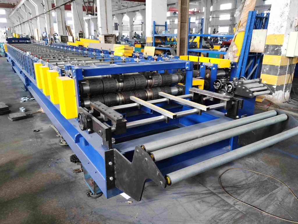
In cellular floor deck roll forming the deck train does the real work. A 3 inch profile needs 20 to 26 stands, shaft diameters of 95 to 120 mm, and a driven pass at every station that carries a bend. The pan train levels, edge forms, and adds a slight crown so the pan sits against the rib flanges.
| Stage | Deck line | Pan line |
|---|---|---|
| Stands | 20 to 26 | 6 to 10 |
| Shaft diameter | 95 to 120 mm | 70 to 95 mm |
| Main drive | 2 to 3 motors, 11 to 22 kW each | 1 motor, 7.5 to 15 kW |
| Line speed | 25 to 40 m/min | 30 to 45 m/min |
| Tolerance to hold | Rib height ±0.8 mm | Flatness 3 mm/m |
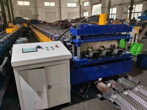
Do not tie the two trains to one drive shaft. Different pass counts and different strip elongation force one of them to slip. Two frames, two gearboxes, one control cabinet, and a hard electrical interlock is the arrangement that survives multi-shift running.
Frame layout follows the weld station. Pan from below puts the deck line high; pan from the side keeps both lines level, easier to service but longer on the floor.
A line that also runs deep-rib or dovetail profiles should plan for cassettes. Our tooling guide covers stand count and roll material for a profile family.
3. Sync at the Register, Not at the Panel End
Speed matching is an encoder problem. The deck line carries the master encoder and the pan line follows through a dancer loop that absorbs the difference during acceleration and coil changes.
Registration happens about 1 m before the first weld head. Two vertical guide rolls push the pan against a datum edge, and a laser confirms the rib centre line against the weld cap. Target is ±1 mm. Beyond 1.5 mm the nugget sits off centre and the cell opens under load.
Two details decide whether registration holds:
- Embossment phasing. Composite cellular deck carries embossments on the rib flanges, and they must land inside the weld footprint. The embossment design guide covers depth and pattern. Phase the embossing stand to the weld cap once, then lock it.
- Camber. Deck camber is limited to about 6 mm in 3 m. Pan camber and deck camber run in opposite directions after welding, so the straightener is set on the assembled panel, not on either strip.
Strip tension changes register as well, so watch the dancer trend.
4. Weld Pitch Caps the Line Speed
A typical cellular schedule uses stitch welds at 12 in (305 mm) pitch, two weld heads, and a nugget diameter of at least 4.8 mm. At that pitch, output settles at 15 to 25 m/min even when both trains can run 40 m/min.
| Weld parameter | Typical setting | Effect when wrong |
|---|---|---|
| Pitch | 12 in (305 mm) | Longer pitch weakens the cell, shorter slows the line |
| Nugget diameter | 4.8 mm minimum | Small nuggets shear at the cell edge |
| Electrode force | 3 to 5 kN | Low force spatters, high force dents the pan |
| Current | Set by gauge pair, not by panel | Fixed current burns through thin pans |
| Dressing interval | Every shift | Skip it and weld size drifts within hours |
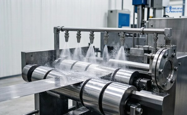
Three habits protect the schedule. Change current and force with the gauge pair, because a 20/20 panel and a 16/16 panel are not the same weld. Dress the copper alloy electrodes every shift, since zinc builds on the face and the operator raises current to compensate. Check cooling water weekly, because hot electrodes mushroom and lose nugget diameter.
Welding is where the price gap between a plain deck line and a cellular line comes from. Two coil lines, one weld station, and the electrical capacity behind them add 30 to 50 percent to the machine budget before tooling.
5. Tooling the Pan Line Really Needs
Buyers underestimate the pan tooling because the pan looks like a flat sheet. Four items carry the quality. Edge form rolls turn a lip so the pan sits inside the deck lap without chafing the zinc. A slitter or trimmer corrects pan width in line to ±0.5 mm, so register does not depend on coil slitting alone. A hardened back-up anvil under each weld head takes electrode force and keeps the pan from deflecting. The cut-off blade shears deck and pan in one stroke, so clearance is set on the combined thickness, up to 2.4 mm, at about 8 percent of that total.
Cutting each strip separately removes the double-thickness shear load and costs one extra station. On a 3 inch profile with 16 gauge deck, that trade pays.

6. Plan Changeover Around the Pan Line
Profile changeover takes 4 to 8 hours, and the pan line is often the reason. The deck train can use cassettes. Pan tooling, weld schedule, register datum, and cut-off clearance all change with the profile.
Sequence the swap: deck tooling, pan tooling, weld heads and schedule, register datum, cut-off clearance, then first-article run. Skipping the register step is how a line welds 3 mm off centre for a whole shift. The quick changeover procedure covers the sequence.
A master gauge panel from the acceptance run cuts the check to minutes. Hang it at the weld station and compare each new setup before releasing the line.
Acceptance Checks Before Sign-Off
Run the first panel through these limits and record the numbers:
- Coverage width 914 ±3 mm, taped at three points.
- Rib height within ±0.8 mm of nominal, at both ends.
- Pan flatness 3 mm per 1 m, straightedge and feeler.
- Camber under 6 mm in 3 m, string line on a flat floor.
- Weld nugget 4.8 mm minimum, peel test on a scrap coupon each shift.
- Cell step under 1 mm at the rib lap, checked by feeler.
Structural acceptance follows the SDI composite deck standard, and the drawing designation should match an SDI 1.5WR or 3W family. Fire ratings come from ASTM E119 assemblies rather than the forming line, so cell depth must match the listed assembly. Diaphragm properties are checked against AISC 360.
Conclusion
Cellular floor deck roll forming is a two-line problem with one bottleneck. Match both coil widths to the developed strip, keep deck and pan on separate trains with one master encoder, register within 1 mm before the weld, and accept that weld pitch caps the line at 15 to 25 m/min.
If the profile is heading toward a 3 inch cell or a 16 gauge deck, read the long span rib rules before ordering tooling. If the question is whether to add cells to an existing line, price the weld station and the second decoiler first.
FAQ
1. What is cellular floor deck roll forming? It is a two-line process that forms a ribbed deck and a flat bottom pan, then welds them into closed cells before cutting to length. The pan acts as a bottom flange, so the panel spans further than a plain deck.
2. How deep are the cells in a cellular deck panel? Cells run 1.5, 2.0, or 3.0 inches (38, 51, or 76 mm), matching deck depth. Cell width follows rib pitch, typically 6 to 12 inches. Deeper cells give more service space and longer unshored spans.
3. What gauge pair should a cellular deck line run? Common pairs are 20/20, 18/20, 18/18, 16/18, and 16/16, written as deck over pan. The pan usually runs one to two gauges lighter. A 16 gauge pan is rare because weld current distorts it.
4. Why do cellular deck lines run slower than plain deck lines? The weld station limits speed, not the forming trains. At a 12 inch pitch with two heads, output settles at 15 to 25 m/min while both trains form at 40 m/min. Adding heads is the usual fix.
5. What weld pitch is used on cellular deck? Twelve inches (305 mm) is the common pitch with a 4.8 mm minimum nugget. Some designs tighten the pitch near panel ends. The structural design fixes the pitch, so line speed follows from it.
6. How is the bottom pan aligned before welding? Guide rolls push the pan against a datum edge about 1 m before the first head, and a laser checks the rib centre line against the weld cap. Target is ±1 mm. Beyond 1.5 mm the nugget sits off centre.
7. Can one line make both plain deck and cellular deck? Yes, if the pan line is a bolt-on module and the weld station can be bypassed. The deck train stays unchanged. The trade is floor space plus 4 to 8 hours of changeover per switch.
8. What causes weld burn-through on the pan? Too much current for the pan gauge, worn electrodes, low electrode force, or poor back-up contact. Zinc build-up on the electrode face is the usual trigger, because resistance climbs and the operator raises current.
9. How long does a profile changeover take? Allow 4 to 8 hours. Deck tooling, pan tooling, weld schedule, register datum, and cut-off clearance all change. Cassettes shorten the mechanical part, but the weld and register checks remain.
10. What standards apply to cellular deck production? Profile and structural acceptance follow the SDI composite deck standard, coating follows ASTM A653, and fire ratings come from ASTM E119. Diaphragm design references AISC 360. The drawing designation defines cell geometry.
Last updated: 2026-11-04
Article Changelog
- 2026-11-02: Initial version for the 2026-11-02 calendar slot. Six double-line techniques, 3 tables, 10 FAQs, gauge and weld data from deck line commissioning.
- 2026-11-04: Added body photos as Elementor image widgets and tightened the acceptance checks.
Next Review Triggers
- SDI or ASTM updates the composite deck standard or the coating designation
- A new weld technology changes the practical line speed ceiling
- Field data shows a different failure mode on 3 inch cellular profiles
- A buyer asks about cellular deck for a market outside North America and Europe



 English