


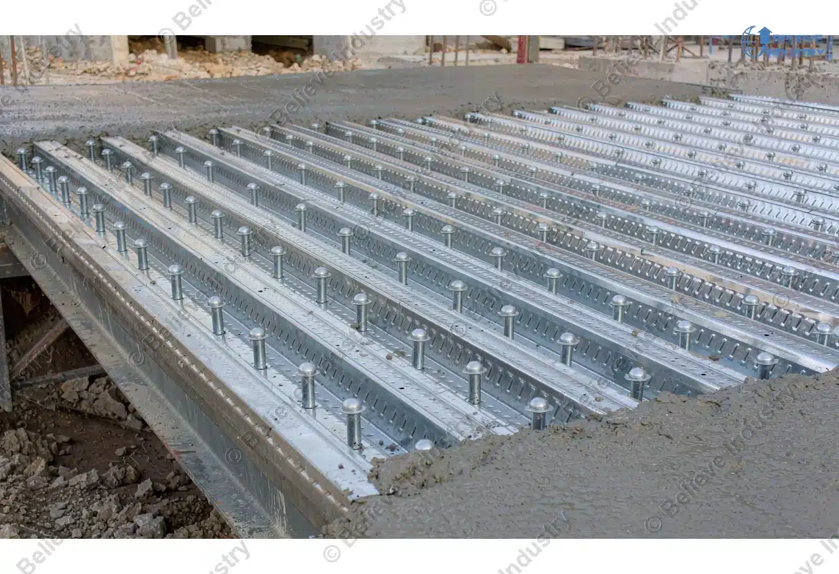
Floor deck shear design values set the safe load a composite slab can carry. This guide lists 5 structural data points engineers verify before and after the concrete pour, from shear stud capacity to deck deflection limits. Beli Rollforming builds the roll forming machines that shape these decks, so the numbers reflect real production, not just code tables.
A floor deck shear design value is a verified resistance or limit, such as stud PRd or slab shear, that confirms the steel sheet and concrete act as one structural member. The five points below cover the interface between steel and concrete, the concrete web itself, and the span rules that decide whether a deck performs as designed. Each one carries a reference you can cite on a submittal.
1. Shear Stud Design Resistance (PRd)
The headed shear stud is the most common connector between the steel beam and the concrete slab. EN 1994-1-1 Clause 6.6.3.1 gives the design shear resistance as the lesser of two values:
PRd = min( 0.8 × fu × π × d² / 4 / γV , 0.29 × α × d² × √(fck × Ecm) / γV )
where fu is the stud ultimate strength, d is the shank diameter, fck is the concrete cylinder strength, Ecm is the concrete modulus, γV is 1.25, and α depends on stud height to diameter ratio.
For a 19 mm stud with fu = 450 MPa in C30/37 concrete, the steel term governs at about 82 kN. The table shows the typical design resistance for the three common diameters.
| Stud diameter | Concrete C30/37 | Design resistance PRd |
|---|---|---|
| 19 mm | C30/37 | 82 kN |
| 22 mm | C30/37 | 109 kN |
| 25 mm | C30/37 | 141 kN |
Profiled steel decking reduces that capacity through a factor kt. For ribs transverse to the beam, EN 1994-1-1 caps kt by the number of studs per rib and the sheet thickness:
| Studs per rib (nr) | Sheet ≤ 1 mm | Sheet ≥ 1 mm |
|---|---|---|
| 1 | 0.85 | 1.00 |
| 2 | 0.70 | 0.80 |
Ribs parallel to the beam use a separate factor, generally lower. Always apply kt, because an unreduced stud table overstates the real connection. Our metal floor deck roll forming machine buying guide explains how embossment and rib geometry feed these connection checks.
2. Steel to Concrete Interface Shear (m-k Method)
Composite action depends on horizontal shear transferred across the steel concrete interface. The m-k method is a codified shear bond check in which m and k are profile specific coefficients measured in full scale slab tests. Both the Steel Deck Institute (SDI, ANSI/SDI C-2017) and EN 1994-1-1 verify this with the m-k method, where the shear bond strength rises with the ratio of slab width to shear span:
V / b = m × (b / L) + k
The m coefficient captures embossment and mechanical keying. The k coefficient captures chemical bond. SDI publishes m and k per deck in psi, while Eurocode research reports them in N/mm². Typical research values for embossed trapezoidal sheet sit near m = 80 to 110 and k = 0.02 to 0.05 in N/mm². Decks without embossments drop sharply, which is why the bond fails without added shear connectors.
| Source / profile | m | k |
|---|---|---|
| Wright, Evans and Harding (1987), chevron emboss | 107.5 | 0.040 |
| Marimuthu et al. (2007), rectangular emboss | 88.0 | 0.032 |
| Corrugated sheet, no emboss | 65.0 | 0.094 |
Embossment rolls must be cut to the bond the profile promises. A few tenths of a millimetre off the embossment depth changes m, and the slab no longer meets the tested value. Our SDI standard roll forming tolerances note shows why rib height control protects that bond.
3. Slab Vertical Shear Capacity (Concrete Web)
The concrete slab also resists vertical shear as a beam web. EN 1992-1-1 gives the design shear without axial load as:
VRd,c = [ 0.18 × k × (100 × ρl × fck)^(1/3) ] × bw × d
where k = 1 + √(200/d) capped at 2, ρl is the longitudinal reinforcement ratio, bw is the web width and d is the effective depth.
ACI 318-19 uses a simpler form for non-prestressed one way members:
Vc = 0.17 × λ × √(fc’) × bw × d
For fc’ = 30 MPa and normal weight concrete (λ = 1), Vc is about 0.93 MPa times bw times d. The steel deck sheet counts as bottom reinforcement, so it raises ρl in the negative moment region and lifts the slab shear capacity where the deck is in tension.
4. Negative Moment Effective Width and Interface Shear
Over interior supports the slab is in negative moment. The concrete compresses over an effective width, and the steel deck pulls in tension. EN 1994-1-1 defines the effective width:
beff = b0 + Σ bei , with bei = min( Le / 8 , bi )
where Le is the equivalent span between zero moment points and bi is the real slab width on each side. For a simply supported bay, Le equals the span L, so bei is L/8 per side.
The longitudinal shear transferred by the studs must be resisted by transverse reinforcement across beff, sized per EN 1992-1-1 Clause 6.21. If the deck rib runs parallel to the beam, the concrete below the rib top is ignored in section resistance, which trims the compression block. Get beff wrong and the negative moment check passes on paper but fails in the field. See how long span floor deck rib depth rules interact with these width checks.
5. Deflection and Span Ratio Limits
Deflection limits decide the result before strength does. SDI practice caps deck deflection under wet concrete at span over 180 or 20 mm absolute, whichever is smaller. Serviceability limits are stricter: L/360 for live load and L/240 for total load are common on office floors.
The concrete above the rib also has a minimum. Most projects place 50 to 75 mm of concrete over the rib top, giving a total slab depth of 130 to 190 mm. Below that, the composite section loses the cover needed for bond and fire. The floor deck profile comparison shows how rib depth and span map to these limits, and the floor deck fire compliance guide adds the fire rating angle.
Conclusion
Floor deck shear design values split into five checks: shear stud PRd of about 82 kN for a 19 mm stud in C30/37, the m-k interface bond, the concrete web shear per EN 1992 or ACI 318, the negative moment effective width, and the L/180 wet concrete deflection limit. Verify each one against the deck profile and the slab detail before the pour. Beli Rollforming builds roll forming machines that hold the embossment and rib tolerances these values depend on, so talk to our team for a profile and tolerance review.
FAQ
1. What are the five floor deck shear design values? The five floor deck shear design values are shear stud PRd, the m-k interface shear bond, the concrete web vertical shear, the negative moment effective width, and the deflection span limit. Each one appears on a composite slab submittal.
2. What is the shear stud design resistance for a 19 mm stud? A 19 mm headed stud with fu = 450 MPa in C30/37 concrete has a design resistance PRd of about 82 kN per EN 1994-1-1. The steel term governs, and profiled decking reduces it through the kt factor.
3. How does the m-k method work for composite decks? The m-k method sets horizontal shear bond as V/b = m × (b/L) + k, where m is the embossment contribution and k is the chemical bond. SDI publishes m and k per deck, and Eurocode research reports them in N/mm².
4. What is a typical m-k value for embossed deck? Typical research values for embossed trapezoidal sheet are m = 80 to 110 and k = 0.02 to 0.05 in N/mm². Decks without embossments fall to m near 65 and need added shear connectors.
5. How do I calculate concrete slab vertical shear? Use EN 1992-1-1 VRd,c = 0.18 × k × (100 × ρl × fck)^(1/3) × bw × d, or ACI 318-19 Vc = 0.17 × λ × √(fc’) × bw × d. The steel deck sheet counts as bottom reinforcement and raises the capacity.
6. What effective width applies in negative moment? EN 1994-1-1 sets beff = b0 + Σ bei, with bei = min(Le/8, bi). For a simply supported bay, Le equals the span, so each side contributes L/8 to the compression width.
7. What deflection limit applies to floor deck under wet concrete? SDI caps deck deflection under wet concrete at span over 180 or 20 mm absolute, whichever is smaller. Serviceability limits are typically L/360 live load and L/240 total.
8. How much concrete cover is needed above the deck rib? Most projects place 50 to 75 mm of concrete above the rib top, giving a total slab depth of 130 to 190 mm. Below that the composite section loses bond and fire cover.
9. Why does profiled decking reduce shear stud capacity? Profiled decking reduces stud capacity through the kt factor because the rib geometry and stud position limit concrete confinement. EN 1994-1-1 caps kt by studs per rib and sheet thickness, down to 0.70 for two studs in a thick sheet.
10. Where can I find standard floor deck shear values? Standard floor deck shear values come from the Steel Deck Institute (SDI) and EN 1994-1-1 for studs and bond, and from EN 1992-1-1 or ACI 318 for slab shear. Beli Rollforming supplies tolerance reviews aligned with these standards.
Last updated: 2026-10-14
Article Changelog
- 2026-10-14: Initial version for the 2026-10-14 calendar slot. 5 shear design data points, 3 tables, 10 FAQs, EN 1994 and SDI references.
Next Review Triggers
- SDI or EN 1994 revises shear stud or m-k guidance
- Beli adds a new embossment pattern that changes m-k values
- A project type drives demand for higher stud density or deeper ribs
- A buyer asks about shear values for a profile not yet covered




 English