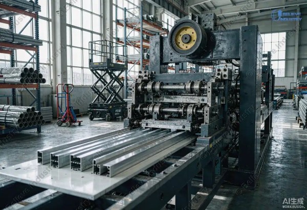











Getting a profile right on paper is not the same as getting it right in production. Most tooling problems trace back to decisions made during product design — before a single roll was turned. Designing products for roll forming demands a different mindset than press brake or extrusion work. The constraints are real, the payoffs are significant, and knowing the rules early saves engineers months of iteration.
George T. Halmos, in the Εγχειρίδιο διαμόρφωσης με ρολό, is direct: “To gain the most benefit from roll forming, it is highly recommended that the product be designed specifically for roll forming.” Products adapted from brake forming or extrusion can usually be re-tooled, but the design should be reviewed before equipment is ordered — even minor changes can reduce production cost or improve structural performance.
This guide works through the seven key engineering decisions that determine whether a roll formed product is efficient to produce and consistent to deliver. Each rule applies whether you are evaluating a new μηχανή σχηματισμού ρολού purchase or reviewing an existing profile that is costing more to produce than it should.
What "Designing for Roll Forming" Actually Means
Roll forming shapes metal strip by passing it through a sequence of roll stations, each one bending the profile incrementally toward its final geometry. Unlike press forming, the material moves continuously. Unlike extrusion, it starts as flat coil stock with defined thickness and mechanical properties.
The consequence: every design decision maps directly to line length, tooling complexity, and achievable tolerance. A profile with tight angular tolerances on multiple bends may require 18 stations instead of 12. A profile designed asymmetrically will fight the tooling at every pass. A minimum bend radius smaller than material thickness will wear out rolls in months.
Designing products for roll forming starts with understanding these connections before finalizing dimensions. Engineers who treat the profile as a finished constraint — rather than as a variable — consistently spend more on tooling and more time on first-article corrections. The process rewards early engagement between product designers and roll tooling engineers.
Rule 1: Define the Cross-Section with Roll Forming Constraints in Mind
Cross-section complexity drives everything downstream — strip width, number of passes, roll diameter requirements, and mill size. Halmos categorizes key cross-section factors that every designer should address:
Section depth. Deep profiles require larger roll diameter differentials between the top and bottom rolls. A 1.5-inch section depth, for example, forces an approximate 3-inch diameter difference between upper and lower rolls at the same station. Ignore this and you get speed differentials that cause strip buckling or surface marking.
Width of flat elements. Wide flat sections between bends are difficult to keep flat. Grooves, beads, or stiffening ribs help control cross-bow, but the tooling to form them adds passes and cost.
Formed vs. stretched grooves. Beads or grooves added for stiffness can be formed (material bent without significant elongation) or stretched (material deliberately thinned). Stretched grooves produce better stiffness but add forming strain. Roll designers need to know which approach applies to set roll geometry correctly.
Symmetry. Symmetric profiles minimize lateral forces. Asymmetric profiles — a Z purlin is the classic example — generate side loads that fight the tooling and require guide rolls, side passes, or edge forming stations to prevent twist. When possible, design profiles with symmetric or near-symmetric cross-sections. If asymmetry is required (as with Μηχανές σχηματισμού κυλίνδρων τεγίδας Z), account for anti-twist provisions in the line layout.
The cross-section review stage is also when designing products for roll forming yields the greatest savings. Halmos points out that even minor cross-section modifications can reduce production cost, add structural performance, or enable secondary operations to be folded into the line.
Rule 2: Set Realistic Tolerances — Tight Tolerances Cost More Than You Think
Tolerance decisions made in the design office directly determine mill length and tooling investment. This is one of the most commonly misunderstood aspects of designing products for roll forming.
Samson Roll Form’s published tolerance guidelines give a working baseline:
| Dimension Type | Standard Tolerance |
|---|---|
| Cross-sectional (fractional) | ±0.031 in. |
| Cross-sectional (decimal) | ±0.010 in. |
| Angular | ±1° |
| Straightness (bow/camber) | 0.015 in./ft |
| Twist | 0.5°/ft |
| Length (≥0.026 in. thick, ≤36 in.) | ±0.015 in. |
| Length (≥0.026 in. thick, 36–96 in.) | ±0.030 in. |
Halmos puts the principle directly: “The tighter the tolerances, the more passes — and better equipment and tooling — are required.” A profile calling for ±0.5° angular tolerance instead of ±1° may require 4 additional finishing passes to achieve consistency. That is a measurably more expensive mill.
Design practice: Specify tolerances based on functional requirements of the end application, not conservative habits from press brake or machining work. If a profile needs to fit into a painted assembly with 0.060-inch total clearance, ±0.031 inch is typically sufficient. Reserve tight tolerances for the dimensions that actually drive fit or function.
Tolerances on hole and notch locations relative to bend lines require separate attention. Pre-punched holes within 1.5× material thickness of a bend line will distort during forming. The correct approach is either to locate holes outside that zone or to accept that hole-to-bend-line tolerances will be looser than hole-to-edge tolerances. Halmos recommends test runs to establish actual pre-punch compensation values before locking in production tooling.
Rule 3: Minimum Bend Radius — The Rule Most Designers Violate
Inside bend radius below material thickness is one of the most common design errors in roll forming. The consequences are not just cosmetic.
Samson’s guidelines state it plainly: “An inside bend radius of less than the material thickness will lessen roll life and increase power requirements.” The roll designer must coin the material to achieve the small radius, which adds forming load, accelerates die wear, and reduces surface quality.
Practical minimums by material:
- Low carbon steel (CQ/DQ), 0.5t–1.0t inside radius — achievable, but expect shorter roll life
- HSLA 50–80 ksi yield, 1.0t–2.0t — springback increases significantly below 1.5t
- Aluminum alloys: softer grades (3003) allow 0.5t; structural grades (6061-T6) require 2.0t–3.0t
- Pre-painted/laminated strip: paint or coating cracking begins around 1t–2t depending on coating type and temperature
For HSLA and high-strength materials, the springback problem compounds the radius problem. At yield strengths above 60 ksi, the material wants to return to a flatter angle after each pass. The tooling must over-bend by 2–15° depending on strength, then allow the profile to spring back to the target angle. Over-bending multiple bends simultaneously creates control problems — operators need to adjust bends independently. Understanding springback στη διαμόρφωση με ρολό and its interaction with bend radius is essential before finalizing cross-section geometry.
The half-thickness rule for inside radius applies to standard production work. Where tight inner radii are structurally required, discuss the design with the roll designer before committing. They can specify a coining pass or an adjusted flower pattern that achieves the radius without excessive die wear.
Rule 4: The Flower Pattern — How the Profile Gets from Flat to Final
The flower pattern (flower diagram) is the engineering document that shows the profile’s cross-section at every forming pass, superimposed on a single plane. It is the central design tool for roll forming and the first thing a qualified tooling engineer produces after the cross-section is finalized.
A well-designed flower pattern:
- Sequences bends in an order that allows the material to move naturally through the mill
- Distributes forming strain evenly across passes to prevent material fatigue
- Avoids simultaneous coining of multiple bends (which creates uncontrollable force combinations)
- Accounts for springback with planned over-bending at the correct pass
General sequencing rules from Roll-Kraft’s documented practice:
- Return flanges (secondary bends) typically begin forming first, reaching approximately 70–80° before the primary web bends start
- The final 10–20° of secondary bend angles is completed after primary bends are established — this reduces distortion at the inner radius
- Forming increments decrease pass-by-pass: early passes carry 15–28° of bend per pass; final passes carry 3–12°
For pre-punched or pre-notched profiles, the sequencing is different. Notched areas near bend lines must be completely formed before the main body bending begins, since later passes will distort the notch geometry. This constraint often adds 2–4 passes to the flower pattern.
The flower pattern also determines the number of passes needed — and therefore the length and cost of the roll forming line. For an μηχανή σχηματισμού ρολού όρθιου ραφιού producing complex warehouse racking uprights with multiple slots and bends, flower patterns routinely run to 18–24 passes. For a simple C channel, 8–12 passes is typical.
Rule 5: Number of Passes — Not a Rule, a Calculation
The number of forming passes required is one of the first questions equipment suppliers ask. It determines mill length, investment cost, and line speed. Halmos puts it bluntly in the Εγχειρίδιο διαμόρφωσης με ρολό: there are no exact equations that govern pass count — it involves engineering judgment calibrated by experience. However, there are calculable factors.
Παράγοντες που αυξάνουν τον απαιτούμενο αριθμό περασμάτων:
| Παράγοντας | Effect |
|---|---|
| Higher material yield strength (>50 ksi) | +2–6 passes for springback control |
| Pre-punched or pre-cut blanks | +2–4 passes (self-feeding requirement) |
| Tight cross-sectional tolerances (±0.010 in.) | +2–4 finishing passes |
| Asymmetric profile geometry | +2–3 passes for twist correction |
| Deep sections (>1.5 in.) | +2–3 passes for edge control |
| Pre-painted or laminated material | +1–2 passes (reduced forming speed, additional care) |
| Multiple secondary bends | +1–2 passes per secondary bend |
For standard low-carbon steel C channel with no pre-punching, 10 passes is a reasonable baseline. A μηχανή διαμόρφωσης μεταλλικών προφίλ for light gauge steel framing (0.5–2.0 mm thickness) typically runs 12–16 passes for C-stud profiles. A μηχανή σχηματισμού ρολού δίσκου καλωδίων handling perforated trough profiles requires 16–22 passes depending on tray width and flange geometry.
Step-up (pass-to-pass diameter increment): Roll-Kraft’s documented practice recommends 0.030 inch diameter step-up per pass for standard applications, reducing to 0.010 inch for thin pre-punched materials. This compensates for the strip’s natural tendency to buckle when fed into a pass at slightly higher speed than the outgoing roll velocity. Too much step-up deforms pre-punched holes; too little causes buckling.
Rule 6: Material Selection Affects Everything in the Tool Design
Designing products for roll forming cannot be separated from material selection. The mechanical properties of the strip determine bend radius, pass count, roll material, lubrication requirements, and achievable tolerances. Halmos is explicit: “Formability of the material may influence the number of forming stands and thus the length of the mill.”
Key material parameters for roll formed product design:
Yield-to-tensile ratio. Low YS/TS ratios (below 0.75) mean the material has more room to deform before fracture — better formability. High-strength low-alloy steels can have YS/TS ratios above 0.90, leaving little margin. The roll designer must account for this in the flower pattern.
Elongation at break. The outside fiber of the strip at any bend point must not exceed the material’s uniform engineering strain. At tight bend radii, this limits how much bend can be achieved per pass.
Thickness tolerance and camber. Materials purchased to broad thickness tolerances (e.g., ±10%) create problems at both extremes. Thin material produces undersized sections and fits loosely in the roll gap. Thick material may seize in the rolls or over-load the mill drive. Strip camber causes pre-punched holes to drift from specified locations. For a thorough breakdown, the guide on επιλογή υλικού για μορφοποίηση με κύλιση covers these interactions with steel and aluminum in detail.
Surface coating. Pre-painted, galvanized, or laminated stock requires different roll surface finishes, lubricants, and forming speeds. Paint cracking starts at bend radii below 1–2× material thickness depending on coating type. Strip preheating to 50–75°C allows tighter bends in some paint systems without cracking. Roll surface hardness specifications for painted material typically run HRC 58–62 to avoid marking.
Για IBR roofing sheet roll forming machines and other high-volume roofing applications, galvanized or pre-painted coil is standard. The product designer must specify coating type and minimum bend radius together — not as separate decisions. The American Galvanizers Association zinc coating thickness standards provide reference data for galvanized coil specifications in roll forming applications.
Rule 7: Secondary Operations Define Product Value, Not Just Machine Configuration
Roll forming’s economic advantage over press forming comes largely from secondary operations integrated into the line. Punching, notching, embossing, welding, and painting all cost more as standalone operations than as in-line processes. Halmos frames this clearly: “Not only should the cross-section be considered; all holes, notches, cutouts, embossments, welding, painting, and packaging should be appraised.”
Designing products for roll forming therefore means designing the entire product, not just the profile shape. Product engineers who lock in hole patterns, coating specs, and assembly interfaces before involving the roll forming line supplier routinely discover expensive conflicts during tooling trials.
Pre-punching (before forming). Holes placed in flat stock before forming are less expensive to punch and maintain better tolerance relative to the strip edges. The trade-off: holes near bend lines will distort during forming. The design solution is to specify hole locations with enough clearance from bend lines (typically ≥1.5t), then use pre-punch compensation testing to establish actual die positions.
In-line punching (tight line vs. loose line). In a tight line, the strip moves continuously and a flying die matches strip speed for punching. In a loose line, the strip is looped and momentarily stopped for stationary pressing. Tight lines are faster but mechanically more complex. For a μονάδα διάτρησης configuration, the choice depends on required hole pattern tolerance, strip thickness, and line speed.
In-line welding. Closed sections — tubes, box beams, and structural hollow profiles — typically require in-line welding. High-frequency resistance welding (HFRW) is standard for continuous tube forming. The product designer must specify weld seam location, material carbon equivalent (for weldability), and post-weld sizing requirements. For automated assembly lines, συγκόλληση σε σειρά for continuous tube forming opens options for structural hollow sections at high volume.
Embossing. Anti-slip patterns on scaffold planks, stiffening ribs on roofing panels, or logo embossing on architectural profiles can all be integrated into the roll forming line. The tooling adds cost but eliminates a downstream operation. For scaffold plank roll forming machines, the emboss pattern is typically formed in a dedicated pass between the main forming stations.
Cutoff type and length tolerance. Length tolerance requirements drive the choice between a simple fixed die, a flying shear, or a servo-synchronized cutoff. Fixed dies require the line to stop for each cut — practical only at low production speeds. Flying shears maintain continuous speed but add mechanical complexity. Σερβοκινητήρας πτήσης ψαλίδι technology, increasingly standard on modern lines, allows ±1–2 mm length tolerance at line speeds up to 30–40 m/min without stopping the strip.
Cross-Section Changes That Reduce Cost Without Compromising Function
The following modifications are commonly suggested by experienced roll designers when reviewing product drawings. Most require minimal or no change to the product’s structural or functional properties:
Increase minimum inside bend radius to 1× material thickness. This alone extends roll life significantly and often reduces the required number of passes by one or two.
Add a small flat width (≥5 mm) between adjacent bends. Eliminating tangent bends (two bends sharing the same radius origin) prevents material pinching and reduces localized strain. It also makes the flower pattern easier to sequence.
Reduce asymmetry. If a profile has an off-center web or unequal flange lengths, consider whether the application actually requires asymmetry. Symmetric profiles require fewer guide passes and produce less twist. The difference in steel use is typically negligible.
Specify standard hole patterns. Custom hole pitches require dedicated punching dies. Standard pitches (50, 100, 150 mm) on strut channel profiles, for example, can often be achieved with multi-tool punching dies, reducing tooling cost substantially for μηχανές διαμόρφωσης καναλιών στήριξης με κύλιση.
Plan for changeover. If the same line will produce multiple profiles or widths, design all profiles to use the same shaft size and forming station pitch. This allows tool sets to share spacers and reduces the investment in changeover hardware. Quick-change roll forming machines can change profiles in 15–30 minutes when the tooling is designed to support it. The Fabricators & Manufacturers Association guidance on quick-change tooling covers cost-benefit analysis for this approach in multi-product facilities.
Shaft Deflection: The Mill Constraint That Products Must Respect
One frequently overlooked constraint in designing products for roll forming is the machine’s mechanical limits. Halmos addresses this directly in Chapter 12: “To produce acceptable products, the roll shaft deflection must be kept within specified limits.”
Shaft deflection depends on:
- Shaft diameter and bearing span
- Material thickness and yield strength
- Number of bends formed at each station
- Distance of bend lines from the bearing supports
A larger shaft diameter reduces deflection but increases roll weight (as a square function of diameter), raises bearing and head costs, and increases the machine’s price. Heavier tooling also slows changeover for multi-product lines.
The practical consequence for product design: profiles combining thick material (≥3 mm), high yield strength (≥60 ksi), and multiple bends at a single station may require an oversized mill or a split-station approach. Reviewing the άξονας για ρολό specifications against the product’s forming load requirements during the design phase prevents the unpleasant discovery that the available machine cannot produce the product to tolerance.
Εξαρτήματα μηχανής διαμόρφωσης κυλίνδρων — specifically roll materials, shaft diameter, and bearing configuration — need to be matched to the product’s material and geometry requirements, not treated as afterthoughts once the profile is frozen. This connection between product design and machine selection is why designing products for roll forming is most efficient when product engineers and equipment suppliers work together from the earliest sketch stage, well before tooling orders are placed.
Quick Reference: Designing Products for Roll Forming
| Design Decision | Standard Practice | Effect if Ignored |
|---|---|---|
| Inside bend radius | ≥1× material thickness | Accelerated roll wear, cracking |
| Ανοχές | Match to functional requirements | Over-specified tolerances add 2–6 passes |
| Hole-to-bend clearance | ≥1.5× material thickness | Hole distortion during forming |
| Profile symmetry | Maximize where possible | Twist, additional guide passes |
| Pre-punching position | Test compensation before production tooling | Hole location errors on finished parts |
| Secondary operations | Integrate into line design | Higher total production cost |
| Shaft deflection | Review against material and bend count | Out-of-tolerance cross-section |
FAQ: Designing Products for Roll Forming
Designing products for roll forming means engineering a metal profile’s geometry, tolerances, material selection, and secondary features specifically to be manufactured on a continuous roll forming line, rather than adapting a design from another process.
Higher yield strength requires larger minimum bend radii, more passes for springback control (typically 2–15° over-bend depending on strength), and heavier mill construction. Products using HSLA steel above 60 ksi should be designed with at least 1.5× inside bend radius and reviewed by a roll designer before tooling is specified.
No. Closed sections with no re-entrant geometry, symmetrical or near-symmetrical profiles, and sections with adequate flat widths between bends are well-suited to roll forming. Re-entrant profiles (where a bend doubles back on itself) require special tooling or may be impractical. Very short flat lengths between bends can cause material pinching.
The flower pattern is a diagram showing the profile’s cross-section at every pass, superimposed on a single plane. It is the primary design document for roll tooling and governs pass count, roll geometry, and forming sequence.
A simple C channel in low-carbon steel: 8–12 passes. A multi-bend structural profile in HSLA steel: 16–20 passes. A complex upright rack column with multiple slots: 18–24 passes. Pass count is set by profile complexity, material strength, tolerances, and whether the strip is pre-punched.
External References
- Halmos, G.T. (Ed.). Εγχειρίδιο διαμόρφωσης με ρολό. CRC Press / Taylor & Francis, 2006. ISBN 978-0-8247-9563-6. Chapter 5 (Roll Design), Chapter 12 (Acquiring Roll Forming Lines).
- AISI Design Guide for Cold-Formed Steel Framing — American Iron and Steel Institute guidance on structural applications of cold-formed profiles
- Samson Roll Form: Tolerance Guidelines — production tolerance standards for commercially roll formed products
- Roll-Kraft: Roll Form Design Overview — detailed tooling design methodology including flower pattern development and K-factor selection
- ASCE 7-22 Minimum Design Loads — governing loads for structural applications of roll formed building products
- Springer: An extension of the flower pattern diagram for roll forming — academic research on forming sequence methodology
- World Steel Association: Steel for packaging and construction — material data and sustainability metrics for roll formed steel products