









Введение
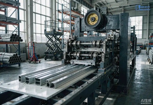
A lipped channel roll forming machine transforms flat steel coil into structural-grade C-sections with return lips. These lipped channels are purlins, girts, wall studs, and floor joists in buildings worldwide. But producing the profile is only half the job. The other half is proving it carries the load.
Every lipped channel roll forming machine output must pass rigorous strength calculations before an engineer stamps the design. Cold-formed steel is thin. It buckles in ways hot-rolled steel does not. A 1.5 mm lipped channel can fail in distortional buckling long before it reaches yield stress.
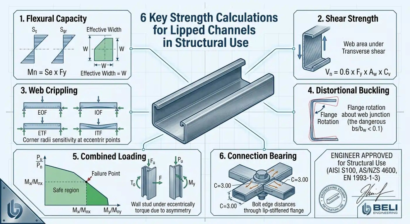
This guide walks through six lipped channel strength calculations that determine whether your profiles are structurally safe. We cover flexural capacity, shear strength, web crippling, distortional buckling, combined loading, and connection bearing. Each calculation references the governing codes: AISI S100, AS/NZS 4600, и EN 1993-1-3.
If you are new to cold-formed steel machinery, start with our C channel roll forming machine overview for foundational profile knowledge.
What Is a Lipped Channel Section?
A lipped channel (or lipped C-channel) is a cold-formed steel section shaped like a C with short return lips at each flange end. The lips stiffen the free edges against buckling. Without them, the flanges buckle locally at very low loads.
Typical dimensions from a lipped channel roll forming machine:
| Параметр | Common Range |
|---|---|
| Web depth (D) | 75–300 mm |
| Flange width (B) | 40–80 mm |
| Lip length (L) | 10–25 mm |
| Толщина (t) | 1.0–3.0 mm |
| Yield strength (Fy) | 250–550 MPa |
The lipped channel roll forming machine controls every dimension. A 0.5 mm error in lip length can shift the distortional buckling stress by 15%. Dimensional precision on the machine directly feeds into lipped channel strength calculations.
For related profile types, see our C purlin roll forming machine и Профилегибочная машина для Z-образных прогонов pages.
1. Effective Section Modulus and Flexural Bending Strength
The first lipped channel strength calculation determines how much bending moment the section resists. Cold-formed compression flanges buckle locally before reaching yield. Engineers use the effective width method.
The nominal flexural strength is:
Mn = Se × Fy
Where Se is the effective section modulus at stress Fy. The effective width of each compression element depends on its slenderness ratio (λ). The ASM International Handbook documents how plate slenderness drives this reduction.
For a lipped channel, the compression flange and lip both get effective width reductions. The web may also be partially effective under high bending. The lipped channel roll forming machine must hold consistent thickness and corner radii, because the effective width calculation uses actual t and inside corner radius.
| Element | Effective Width Factor |
|---|---|
| Compression flange (stiffened) | b = 1.64 × t × sqrt(E/Fy) / λ |
| Lip (unstiffened) | b = 0.43 × t × sqrt(E/Fy) |
| Web (in bending) | Variable per stress gradient |
A lipped channel roll forming machine with hardened rollers maintains corner sharpness. Rounded corners from worn tooling reduce effective flange width and lower bending capacity silently.
2. Web Shear Capacity
The second lipped channel strength calculation checks whether the web can resist transverse shear forces. Lipped channels used as beams carry shear through the web. Thin webs buckle in shear before yielding.
The nominal shear strength per AISI S100 uses:
Vn = 0.6 × Fy × Aw × Cv
Where Aw is the web area (h × t) and Cv is the shear buckling coefficient. For h/t ≤ 2.33 × sqrt(E/Fy), the web yields in shear and Cv = 1.0. For higher slenderness, Cv drops below unity.
Research from Thin-Walled Structures journal shows that lipped channel webs benefit from additional fixity at the web-flange junction. This raises the shear buckling coefficient above the classical k = 5.0.
A lipped channel roll forming machine must maintain uniform web thickness. Gauge variation along the length creates weak shear zones. The machine’s roll gap consistency governs this tolerance.
3. Web Crippling Under Concentrated Loads
The third lipped channel strength calculation addresses local web failure under point loads or reactions. This is web crippling. It is the most common failure mode for cold-formed purlins at support points.
The nominal web crippling strength depends on load position:
| Load Case | Описание |
|---|---|
| End-One-Flange (EOF) | Load at edge, reaction at support |
| Interior-One-Flange (IOF) | Load away from edge |
| End-Two-Flange (ETF) | Two loads at edge |
| Interior-Two-Flange (ITF) | Two loads in span |
Each case uses a different empirical formula in AISI S100. The general form is:
Pn = C × t² × Fy × (N/t)0.5 × (h/t)0.25
Where N is the bearing length and h is the flat web depth. The coefficient C varies by load case and section type. AS/NZS 4600 provides tabulated C values for lipped channels.
Web crippling is sensitive to the inside bend radius at the web-flange corner. A lipped channel roll forming machine producing tight, consistent corners (R ≤ 2 × t) gives higher web crippling capacity. Oversized radii from worn rolls reduce bearing area and lower crippling strength.
For inline joining methods after roll forming, see our guide on roll forming welding methods.
4. Distortional Buckling Strength
The fourth lipped channel strength calculation is the most critical for this section type. Distortional buckling occurs when the compressed flange-lip assembly rotates about the web-flange junction. The flange and lip move outward. The web bends transversely. This failure mode is unique to open thin-walled sections.
The Direct Strength Method (DSM) in AISI S100 calculates distortional buckling strength:
Md = My × (Mcrd / My)0.5 × [1 – 0.22 × (Mcrd / My)0.5]
Where Mcrd is the elastic distortional buckling moment and My is the yield moment. The ratio Mcrd/My determines whether the section fails in distortional buckling or reaches yield. When Mcrd/My < 0.56, distortional buckling governs.
Research published in ScienceDirect confirms that flange-to-web width ratio (bf/bw) and lip-to-web ratio (bs/bw) are the dominant geometric parameters. For typical lipped channels, bf/bw ranges from 0.2 to 1.0 and bs/bw from 0.1 to 0.4.
| Geometry Ratio | Distortional Buckling Risk |
|---|---|
| bf/bw < 0.3 | Low risk |
| bf/bw 0.3–0.6 | Moderate risk |
| bf/bw > 0.6 | High risk — needs check |
| bs/bw < 0.1 | Lips too short — high risk |
| bs/bw 0.15–0.25 | Optimal lip length |
| bs/bw > 0.35 | Lips too long — local buckling |
A lipped channel roll forming machine must produce lip lengths within the optimal range. If the lip is too short, distortional buckling governs at low loads. If too long, the lip itself buckles locally. The machine’s roll tooling design sets the lip length precisely and repeatably.
For high-speed production of multiple C and Z profiles, see our high-speed C/Z purlin roll forming machine.

5. Combined Axial Compression and Bending Interaction
The fifth lipped channel strength calculation checks members under simultaneous compression and bending. Wall studs and eccentrically loaded columns experience this combined loading. The AISI S100 interaction equation is:
Pu / Pn + Mx / (Mnx × α) + My / (Mny × α) ≤ 1.0
Where Pn is the nominal axial capacity, Mnx and Mny are nominal bending capacities, and α accounts for second-order effects. For lipped channels, the eccentricity between centroid and shear center creates additional torque. The Американский институт чугуна и стали requires this effect for singly-symmetric sections.
The lipped channel roll forming machine role is dimensional symmetry. If left and right flanges differ by even 1 mm, the shear center shifts. This increases torque and reduces combined capacity. Machine precision on both sides of the profile is non-negotiable.
6. Connection Bearing and Lip-Stiffened Capacity
The sixth lipped channel strength calculation evaluates bolted connections through the web or flange. These connections must resist bearing, tear-out, and net section rupture.
The nominal bearing strength per AISI S100 is:
Pn = C × fu × t × d
Where fu is the ultimate tensile strength, t is thickness, d is bolt diameter, and C depends on edge distance and whether the element is stiffened. A lip-stiffened flange gets a higher C, but only if the lip is properly formed.
| Connection Detail | Bearing Coefficient C |
|---|---|
| Unstiffened flange | 2.22 (minimum) |
| Lip-stiffened flange | 2.80–3.00 |
| Two-bolt web connection | Per net area check |
| Screw connection | Per AISI S200 |
The lipped channel roll forming machine determines whether the lip qualifies as a stiffener. A poorly formed lip fails to provide the stiffening effect. The machine must hold the lip angle at 90° ±2° for the bearing coefficient to apply.
For material specs governing connection strength, ASTM A653 defines mechanical properties of galvanized steel coil.
Machine Specifications and Beli Engineering
A lipped channel roll forming machine producing structural-grade profiles must meet these specifications:
| Параметр | Structural Grade | Non-Structural |
|---|---|---|
| Thickness tolerance | ±0.03 mm | ±0.08 mm |
| Dimensional tolerance | ±0,3 мм | ±0,5 мм |
| Lip angle | 90° ±2° | 90° ±5° |
| Corner radius | R ≤ 2.0 × t | R ≤ 3.0 × t |
| Формировочные станции | 22–28 | 14–18 |
| Скорость линии | 15–25 m/min | 8-15 м/мин |
| Cut method | Servo flying saw | Hydraulic shear |
Structural profiles demand more forming stations. More stations mean gradual bending. Gradual bending reduces residual stress and springback. This is critical for lipped channel strength calculations because residual stress lowers the effective yield in buckling zones.
Believe Industry has over 15 years of experience building lipped channel roll forming machines. Our lines serve clients across 20+ countries, with main markets in the US, Europe, and Australia. Three features matter most: D2 tool steel rollers hardened to HRC 58–62 for corner sharpness, servo-driven roll gap control holding ±0.03 mm thickness, and springback compensation adjusting forming angles per coil batch. For roller material details, see our roll forming roller materials comparison.
Заключение
A lipped channel roll forming machine does more than shape steel. It creates structural members that buildings depend on. The six lipped channel strength calculations (flexural, shear, web crippling, distortional buckling, combined loading, and connection bearing) determine whether those members are safe.
Each calculation traces back to dimensional precision on the machine. Thickness tolerance feeds effective width. Corner radius feeds web crippling. Lip length feeds distortional buckling. Lip angle feeds connection bearing. A machine that cannot hold tolerances produces profiles that fail calculations before they see a load test.
Three takeaways:
- Distortional buckling is the governing failure mode for lipped channels. Lip length and flange width ratios matter most. Your lipped channel roll forming machine must produce consistent geometry across the optimal ratio range.
- Effective width reductions apply to every compression element. Thickness consistency and corner sharpness determine how much capacity you lose to local buckling.
- Connection strength depends on lip quality. A poorly formed lip forfeits the stiffened bearing coefficient. The machine must deliver 90° ±2° at production speed.
Believe Industry builds lipped channel roll forming machines that meet these demands. Every line passes full-speed FAT before shipment. Contact us at enquiry@believeindustry.com to discuss your structural lipped channel production requirements.
Часто задаваемые вопросы
For structural applications, the machine should handle 1.2 mm minimum. Most building codes require at least 1.0 mm for load-bearing cold-formed steel. Typical structural gauges run 1.5–2.5 mm. The machine must hold ±0.03 mm tolerance across this range.
Distortional buckling typically governs for lipped channels in bending. For axially loaded wall studs, the combined axial-bending interaction often controls. Web crippling governs at support reactions and point loads. An engineer must check all six.
Yes. A multi-profile lipped channel roll forming machine with adjustable guide widths and interchangeable cassette tooling switches between web depths (75–200 mm) and flange widths. Tooling changeover takes 2–4 hours with cassette-type roll stands.
G250 (250 MPa) is the minimum for general structural use. G350 (340 MPa) and G450 (450 MPa) are common for purlins and girts. Higher grades like G550 reduce thickness but increase distortional buckling risk. The lipped channel roll forming machine must be configured for the target grade’s springback behavior.
Lip length directly controls distortional buckling stress. Too short (bs/bw < 0.1) and the lip cannot restrain the flange. Too long (bs/bw > 0.35) and the lip itself buckles locally. The optimal range is bs/bw = 0.15–0.25. The lipped channel roll forming machine must hit this target within ±1 mm.
AS/NZS 4600 governs cold-formed steel design. AS 1397 governs the galvanized coil material. AS 4100 provides supplementary steel structure rules. The machine must produce profiles satisfying all three. For details, see Standards New Zealand.
The DSM applies to flexural capacity, distortional buckling, and axial capacity. It does not cover web crippling or connection bearing directly. Those use separate empirical formulas in AISI S100.
Structural-grade lines typically run 15–25 m/min. Higher speeds require servo-driven flying cut systems. Speed above 30 m/min risks thermal expansion affecting dimensional tolerance. For most producers, 20 m/min balances output and quality.
For structural use, the inside corner radius should not exceed 2.0 × t. Tighter corners improve web crippling capacity and effective flange width. The machine’s roll gap and springback settings control this parameter.
Yes, with modifications. The effective width method still applies. However, stainless has higher strain hardening and a lower elastic modulus (193 GPa vs 200 GPa). AS/NZS 4673 provides stainless-specific provisions. The lipped channel roll forming machine needs specialized stainless steel tooling for these profiles.
Список изменений статьи
- 2026-08-03: Initial publication. Covered 6 strength calculations for lipped channel roll forming machine outputs, referencing AISI S100, AS/NZS 4600, and EN 1993-1-3. Included machine spec table, standards comparison, and 10 FAQs.
Триггеры следующего обзора
- AISI S100 or AS/NZS 4600 publishes a new revision affecting lipped channel design rules
- New distortional buckling DSM equations are adopted into a governing standard
- Believe Industry releases a new lipped channel roll forming machine model with updated specs
- New research on advanced high-strength steel lipped channels changes the effective width approach
- EN 1993-1-3 publishes a revision that changes cold-formed section design methodology