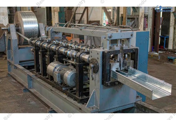



Roller gap clearance decides whether a profile comes out straight or goes to scrap. It is the distance between the upper and lower forming rolls at each stand. Set it wrong and you fight defects for the whole shift.
Most operators set gaps once during installation and never touch them again. That habit causes most of the quality drift on a line.
This guide covers six material thickness compensation rules for roll forming roller gap clearance. You will get starting values, measurement methods, and the exact moment to tighten or loosen each stand.
Correct roll forming roller gap clearance is a repeatable setting, not a feel. Herramientas de perfilado setup starts here. For the full machine picture, read the componentes de la perfiladora guía.
What Is Roll Forming Roller Gap Clearance?
holgura de la separación de rodillos is the space between the upper and lower rolls of one forming stand, measured with the rolls closed and no strip between them. It defines how much the material is guided, squeezed, or left free at each pass.
Three relationships control everything:
- Gap larger than the strip: the material floats, edges wave, springback grows.
- Gap smaller than the strip: the rolls squeeze, the material thins and scratches.
- Gap close to the strip: the material is guided, dimensions hold.
Three forces change the effective clearance during production. Incoming coil thickness varies. Rolls heat up and grow. Rolls wear down. Each force needs its own compensation rule.
Roll forming roll design fixes the starting gap on paper. This guide explains how to manage roll forming roller gap clearance in real production conditions.
The 6 Material Thickness Compensation Rules
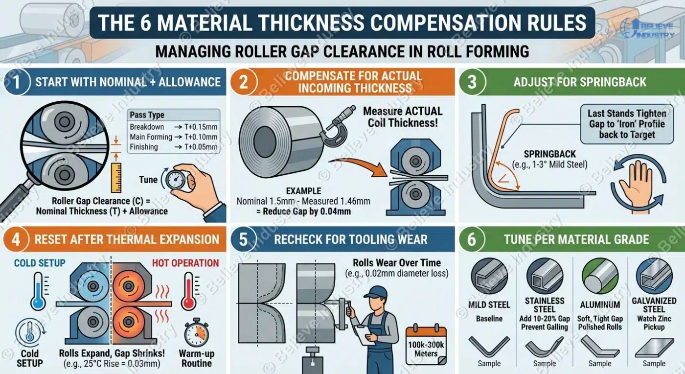
Rule 1: Start Roll Forming Roller Gap Clearance from Nominal Gauge Plus an Allowance
Never set a forming pass roller gap clearance exactly at nominal thickness. The strip needs room to flow, or the rolls scuff and thin it.
Use these starting points on a new tooling set:
| Pass Type | Starting Gap | Objetivo |
|---|---|---|
| Guide and idle passes | Nominal + 0.30 to 0.50 mm | Hold the strip without touching it |
| Breakdown passes | Nominal + 0.10 to 0.20 mm | Start edge bending, allow metal flow |
| Main forming passes | Nominal + 0.05 to 0.15 mm | Control shape, avoid thinning |
| Sizing and finishing passes | Nominal + 0.00 to 0.05 mm | Fix final dimension, iron the profile |
Then tune in 0.05 mm steps. Run a test strip, measure the profile, adjust one stand at a time. This baseline applies to every material thickness compensation job that follows.
Rule 2: Compensate Roll Forming Roller Gap Clearance for Actual Incoming Thickness
Coil gauge is never exactly nominal. Coil suppliers roll to a tolerance band, not to a single number.
Under ASTM A568/A568M, cold rolled strip commonly runs within plus or minus 5 percent of nominal thickness. Hot rolled can vary plus or minus 10 percent. A 1.5 mm coil may measure anywhere from 1.42 to 1.58 mm.
Measure the actual coil with a micrometer before setup. Compare it to nominal. Apply the difference to every stand.
Example: nominal 1.5 mm, measured 1.46 mm. Reduce every starting gap by 0.04 mm. Skip this step and the first 200 meters run with 0.04 mm of unintended squeeze, which shows up as thinning and scratches.
Set the roller gap clearance from the measured value, not the purchase order. It takes five minutes with a micrometer and saves a full coil of rejects. This is the purest form of material thickness compensation.
Rule 3: Adjust Roller Gap Clearance for Springback
Springback is the elastic recovery of the strip after forming. The steel springs partway back from the bend angle the rolls create. See the ASTM A568/A568M standard for gauge tolerance context.
Mild steel springs back 1 to 3 degrees per bend. High strength steel springs back more. Stainless steel SS304 and SS316 can double that figure. Industry guidance from MetalForming Magazine shows that springback control starts with the last stands.
Springback widens flange angles and changes leg dimensions. Operators compensate in two ways. They overbend in the roll profile, or they tighten the final stand gap so the last pass irons the material back to target.
If your flange angles run open, reduce the roller gap clearance on the last two stands by 0.05 to 0.10 mm. Re-run the test strip. Repeat until the angle lands on print.
Nuestro recuperación elástica en el perfilado guide explains the four main control techniques in depth.
Rule 4: Reset Roller Gap Clearance After Thermal Expansion
Rolls heat up as the line runs. Heat changes the gap.
Friction at the forming interface raises roll temperature 15 to 30 °C above shop temperature during a continuous run. A 200 mm diameter roll grows about 0.03 mm for every 25 °C of temperature rise. The gap shrinks by the same amount.
A cold line set at nominal plus 0.10 mm can run at nominal plus 0.07 mm after two hours, then drift tighter as the shift continues.
Fix it with a warm-up routine. Run the line empty or at low speed for 20 to 30 minutes. Set the roller gap clearance at operating temperature. Re-check at shift start and after long breaks.
Rule 5: Recheck Roller Gap Clearance for Tooling Wear
Rolls wear, and worn rolls change the effective roller gap clearance.
Flange rolls lose 0.02 to 0.05 mm of diameter over hundreds of thousands of meters. That wear shifts profile dimensions by 0.1 mm or more, enough to fail a tolerance check.
Build gap checks into your maintenance schedule. Re-verify the roller gap clearance on every stand every 100,000 to 300,000 linear meters, or every one to two weeks on a busy line. Tooling suppliers such as Roll-Kraft publish the same re-gap cadence for their tooling sets.
When wear exceeds the adjustment range of the shims or eccentrics, the rolls need regrinding or replacement. See our mantenimiento preventivo del proceso de laminado guide for full schedules, and the inspección de perfilado checklist for what to measure.
Rule 6: Tune Roller Gap Clearance per Material Grade
Different materials behave differently under the same roller gap clearance.
Stainless steel work hardens and galls easily. It needs 10 to 20 percent more gap allowance than carbon steel in the same pass. Aluminum is soft and marks easily, so it needs tight, clean gaps with polished rolls. Galvanized steel carries a zinc coating that transfers to the rolls when the gap is too tight.
Start with these values on a 1.0 mm strip:
| Material | Breakdown Gap | Forming Gap | Notas |
|---|---|---|---|
| Mild steel St37/St52 | Nominal + 0.15 mm | Nominal + 0.10 mm | Standard baseline |
| Galvanized steel G90 | Nominal + 0.15 mm | Nominal + 0.10 mm | Watch zinc pickup, keep gaps clean |
| Stainless steel SS304/316 | Nominal + 0.18 mm | Nominal + 0.12 mm | 10-20% more gap, prevents galling |
| Aluminum 5052 | Nominal + 0.10 mm | Nominal + 0.05 mm | Soft, tight gap, polished rolls |
Rule 6 connects to material selection. The material de perfilado comparison covers steel versus aluminum, and the stainless steel roll forming guide details the special tooling needs. Roller steel grade matters too, so review the comparación de materiales de rodillos.
How to Measure and Set Roller Gap in 6 Steps
A feeler gauge is the standard tool. It reads to 0.01 mm and works on most stands. For loaded gaps under pressure, use the lead wire method: place a short wire across the roll face, close the rolls, and measure the flattened wire.
- Stop the line and lock out the drive. Follow lockout tagout (LOTO) procedures before any adjustment.
- Clean the roll faces. Dirt and oil change the reading.
- Insert the feeler gauge at the roll center line and at both ends of the roll face.
- Compare each reading to the target chart for that pass.
- Adjust the gap with shims, eccentric sleeves, or screw-downs. Turn only one stand at a time.
- Run a test strip. Measure the profile with a caliper. Repeat until the dimensions land on print.
Record every setting. A written gap chart turns a random setup into a repeatable procedure. Consistent roll forming roller gap clearance starts with measurement discipline.
Roller Gap Troubleshooting Table
Use this table when a roller gap clearance problem appears on the line.
| Defecto | Most Likely Cause | Gap Correction |
|---|---|---|
| Edge wave on one side | Gap too loose on that side | Tighten that stand by 0.05 mm |
| Rayones superficiales | Gap too tight, pickup on rolls | Loosen 0.05 mm, clean the rolls |
| Profile thinning | Gap below material thickness | Loosen to nominal plus allowance |
| Open flange angle | Springback not compensated | Tighten last two stands 0.05-0.10 mm |
| Dimension drift over a shift | Thermal expansion not reset | Re-check gaps after warm-up |
If defects persist after gap correction, suspect the roll profile itself. A cambio de perfil is the right time to re-verify every clearance from scratch. Production experience from The Fabricator confirms that most setup problems trace back to the tooling gap, not the machine.
Preguntas frecuentes
holgura de la separación de rodillos is the space between the upper and lower rolls of one forming stand, measured with the rolls closed and no material between them. It controls how much the strip is guided, squeezed, or left free at each pass.
Most forming passes start at nominal material thickness plus 0.05 to 0.15 mm, while guide passes run at plus 0.30 to 0.50 mm. The exact value depends on material grade, pass function, and line speed.
A too tight roller gap squeezes the strip, causing material thinning, surface scratches, and zinc pickup on coated steel. In severe cases it stalls the line or permanently marks the rolls.
A too loose roller gap lets the strip float between rolls, producing edge wave, profile bow, and unstable dimensions. Springback also increases because the last stands no longer control the material.
You measure roller gap clearance with a feeler gauge at the roll center line and at both ends of the roll face, or with the lead wire method for loaded gaps. Feeler gauges read to 0.01 mm accuracy.
Yes. Cold rolled strip can vary plus or minus 5 percent from nominal and hot rolled up to plus or minus 10 percent, so a 1.5 mm coil may actually measure 1.42 to 1.58 mm. Measure the real thickness and shift every gap by the difference.
Tighten the last two forming stands by 0.05 to 0.10 mm so the final passes iron the flange back to the target angle. Mild steel springs back 1 to 3 degrees per bend, and stainless can double that.
Recheck the roller gap clearance on every stand every 100,000 to 300,000 linear meters, or every one to two weeks on a continuous line. Also re-verify after warm-up, after tooling changes, and whenever a defect appears.
Stainless steel SS304 and SS316 need 10 to 20 percent more gap allowance than carbon steel in the same pass to prevent galling and work hardening marks. Start at nominal plus 0.12 to 0.18 mm on a 1.0 mm strip.
No. Guide passes run loose at nominal plus 0.30 to 0.50 mm, breakdown passes at plus 0.10 to 0.20 mm, and sizing passes tightest at nominal to plus 0.05 mm. Each pass has a different job.
Conclusión
holgura de la separación de rodillos is the highest-leverage setting on a roll forming line. Get it right and profiles stay on tolerance all shift. Get it wrong and every defect in the book appears.
Start from nominal gauge plus an allowance. Compensate for real coil thickness, springback, heat, and wear. Tune per material grade. Re-measure on a schedule.
These six material thickness compensation rules are simple to apply. They convert setup from guesswork into a repeatable procedure that any operator can follow.
When you upgrade a line or buy a new machine, ask the supplier for a documented gap chart for every profile. Beli Rollforming has built custom roll forming machines for customers in 20+ countries over the past 15+ years. Every machine ships with tooling documentation and setup support. Contact us about your next máquina perfiladora.