









Edge wave prevention in roll forming decides whether your profile ships to the customer or goes to the scrap bin. Edge wave, also called wavy edges, shows up as a rippled strip edge that will not lie flat on a surface plate. It is one of the most common roll forming defects on wide, thin profiles, and in most cases the root cause sits in the entry section, not in the forming rolls themselves.
The mechanism is simple. Roll forming bends the strip edge through a longer path than the strip center. If the edge fibers elongate more than the center fibers, the extra length buckles into a wave. Strip tension control is the engineering lever that keeps that elongation inside the flatness tolerance before the strip reaches the first forming stand. This guide breaks down five strip tension control rules, with numbers, tables, and troubleshooting steps you can apply today.
What Is Edge Wave and Why Strip Tension Causes It
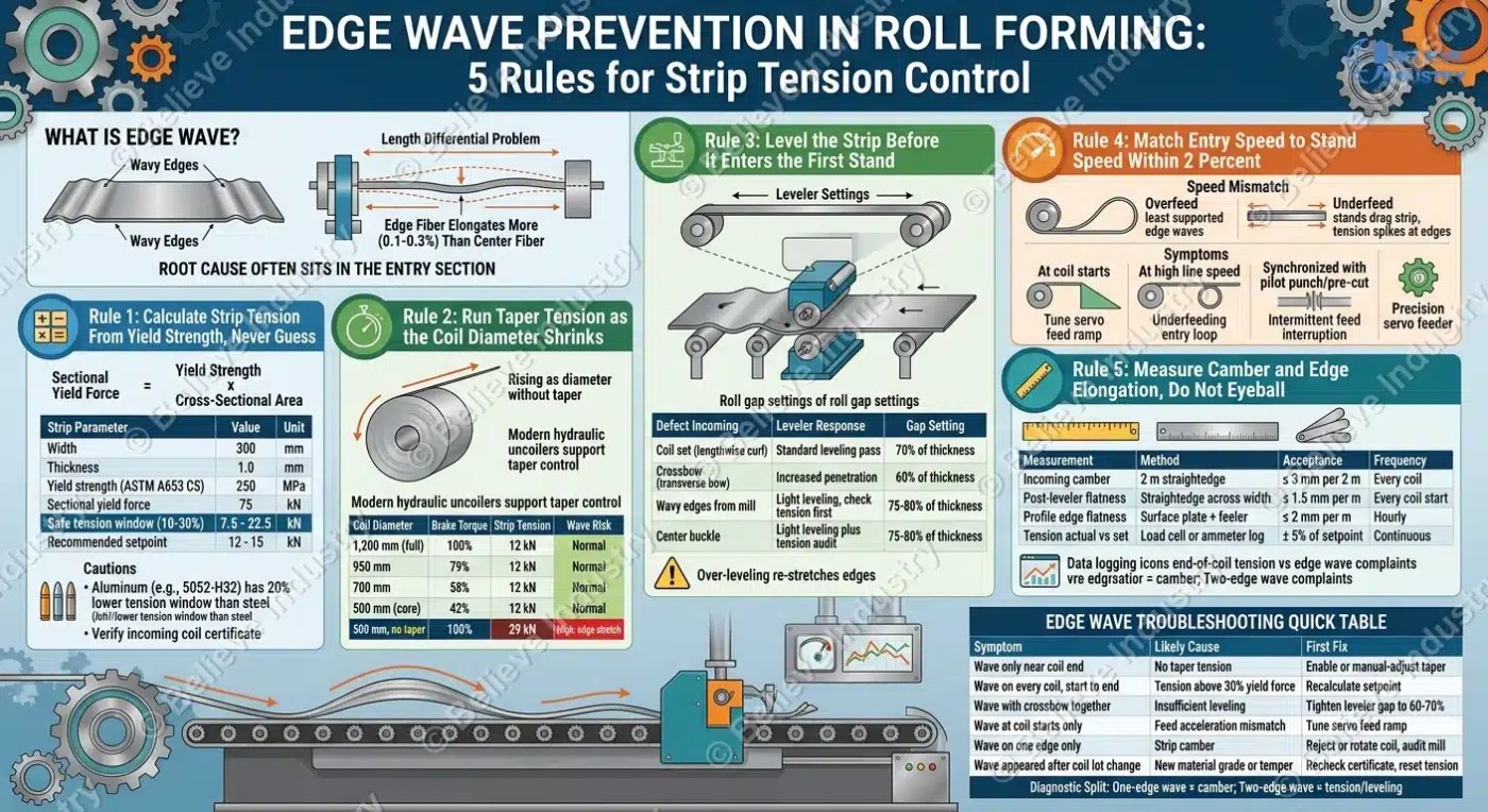
Edge wave is a flatness defect where the strip edges form lengthwise waves while the center stays flat. It is a length differential problem: when the edge fiber of the strip is even 0.1 to 0.3 percent longer than the center fiber, the edge cannot stay straight and buckles.
Three entry-section problems drive that length differential:
- Excessive or unstable strip tension. Over-tensioned strip stretches plastically near the edges, especially on low-yield materials like annealed steel or soft aluminum.
- Coil set and crossbow. A coil that came off the mill with residual stress uncoils unevenly, feeding pre-stretched edges into the former. A proper مستوي تشكيل اللفة removes this memory before forming.
- Speed mismatch. If the entry feeder or uncoiler pushes strip faster than the forming stands pull it, the slack accumulates and the edge waves first because it is the least supported zone.
Cold-rolled steel supplied to ASTM A653 is the most common roll forming input, and it arrives with its own flatness tolerance from the producing mill. For edge wave prevention in roll forming, your line must not add elongation on top of what the mill already allowed. The آلة التسوية entry section is where you take that mill memory out.
Rule 1: Calculate Strip Tension From Yield Strength, Never Guess
The first rule of strip tension control is arithmetic, not feel. Strip tension should stay between 10 and 30 percent of the strip’s sectional yield force. Below 10 percent the strip wanders and camber develops. Above roughly 30 percent, soft materials plastically stretch and the edges elongate permanently, which plants edge wave before forming even starts.
Sectional yield force equals yield strength multiplied by cross-sectional area. For a 300 mm wide, 1.0 mm thick steel strip with 250 MPa yield strength, the yield force is 75 kN, so the working tension window is 7.5 to 22.5 kN. Convert that to uncoiler brake torque using the current coil diameter, and you have a setpoint instead of a guess.
| Strip Parameter | Value | Unit |
|---|---|---|
| عرض | 300 | مم |
| السُمك | 1.0 | مم |
| Yield strength (ASTM A653 CS) | 250 | MPa |
| Sectional yield force | 75 | kN |
| Safe tension window (10-30%) | 7.5 – 22.5 | kN |
| Recommended setpoint | 12 – 15 | kN |
Two cautions. Aluminum alloys like 5052-H32 run a yield strength near 195 MPa, so the same geometry carries a tension window 20 percent lower than steel. And verify the incoming coil certificate rather than assuming the grade, because a full-hard coil tolerates far more tension than an annealed one. This calculation is the foundation of edge wave prevention in roll forming, and it takes ten minutes with a coil data sheet.
Rule 2: Run Taper Tension as the Coil Diameter Shrinks
A coil at full diameter has a large lever arm, so a fixed brake torque produces one tension level. As the coil unwinds toward the core, the same torque produces tension that climbs inversely with diameter. On a coil running from 1,200 mm down to 500 mm outer diameter, torque held constant makes final-coil tension 2.4 times higher than start-of-coil tension. That spike over-stretches the last third of every coil, which is why edge wave often appears “only near the end of the coil.”
The fix is taper tension: the brake control reduces torque in proportion to shrinking coil diameter so strip tension stays constant. Modern hydraulic uncoilers like the آلة فك الملفات الهيدروليكية سعة 5 أطنان support diameter-tracking taper control, and the آلة تشكيل اللفائف وفك اللفائف guide covers the two functional types in detail.
Practical taper settings that work on production lines:
| Coil Diameter | Brake Torque | Strip Tension | Wave Risk |
|---|---|---|---|
| 1,200 mm (full) | 100% baseline | 12 kN | Normal |
| 950 mm | 79% | 12 kN | Normal |
| 700 mm | 58% | 12 kN | Normal |
| 500 mm (core) | 42% | 12 kN | Normal |
| 500 mm, no taper | 100% | 29 kN | High: edge stretch |
If your uncoiler lacks automatic taper, schedule manual torque checks every quarter coil and log them. That habit is cheap strip tension control with immediate flatness payback.
Rule 3: Level the Strip Before It Enters the First Stand
Coil set, crossbow, and residual mill stress all feed pre-existing length differences into the roll former. Leveling removes them. A leveler, sometimes called a flattener, works the strip through alternating bend cycles that plasticize the fiber stresses and equalize edge-to-center length. On thin, wide, or cosmetic profiles, a leveler is not optional equipment; it is the difference between a flat part and a reject.
The key setting is roll gap. Set the entry leveling gap to 60 to 80 percent of strip thickness for the first pass, then open in small increments until flatness checks pass. Over-leveling (gap too tight) re-stretches the edges and recreates the wave you were removing, so the direction of adjustment matters as much as the number.
| Defect Incoming | Leveler Response | Gap Setting |
|---|---|---|
| Coil set (lengthwise curl) | Standard leveling pass | 70% of thickness |
| Crossbow (transverse bow) | Increased penetration | 60% of thickness |
| Wavy edges from mill | Light leveling, check tension first | 75-80% of thickness |
| Center buckle | Light leveling plus tension audit | 75-80% of thickness |
Note the third row: if the coil arrives with edge wave from the producing mill, leveling alone is a band-aid. Audit your tension per Rule 1 and contact the coil supplier. المُصنِّع documents how incoming coil quality limits what any downstream line can recover, so honest material acceptance criteria belong in every roll forming quality plan.
Rule 4: Match Entry Speed to Stand Speed Within 2 Percent
The strip between the uncoiler and the first forming stand is a free loop. If the entry section overfeeds, the loop grows and the strip edge, which has the least lateral support, waves first. If the entry section underfeeds, the stands drag the strip and add tension spikes that peak at the edges. Both failure modes are speed mismatch problems, and both are preventable.
The engineering rule: keep entry feed speed and first-stand line speed matched within 2 percent at steady state. A line running 30 m/min should feed between 29.4 and 30.6 m/min. Larger mismatches either pile up slack or spike tension with every coil start, weld seam passage, or speed change. A precision وحدة تغذية المؤازرة holds ±0.01 mm feed accuracy and, more importantly for flatness, holds that accuracy through speed transitions instead of surging.
Check these three speed-mismatch symptoms during your next run:
- Edge wave that appears at coil starts and fades after 30 seconds points to feed acceleration tuning, not roll tooling.
- Edge wave that worsens at high line speed points to an underfeeding entry loop.
- Edge wave synchronized with the pilot punch or pre-cut shear points to intermittent feed interruption.
Each symptom has a different fix, but all three live in the entry section. Sorting them out before touching the forming rolls saves days of misdirected troubleshooting. This is one of the مكونات آلة تشكيل اللفائف disciplines that separates stable lines from chronic edge wave lines.
Rule 5: Measure Camber and Edge Elongation, Do Not Eyeball
You cannot control what you do not measure. The final rule of strip tension control is instrumentation: check incoming camber, check strip flatness after leveling, and check finished profile flatness on a surface plate at set intervals. Camber, the sideways curvature of the strip edge, is measured with a 2 m straightedge along the concave edge; standard acceptance is under 3 mm of deviation over 2 m on decent mill supply.
Edge elongation you measure indirectly through flatness. Lay the cut profile on a flat table and check gap under a straightedge across the width and along each edge. For most architectural and racking profiles, a flatness tolerance of 2 mm over any 1,000 mm span keeps the part saleable, consistent with the mill tolerance framework that AISC and ASTM publish for structural steel products. Instrumented lines add laser flatness measurement after the leveler, catching trends before operators can see them.
| Measurement | طريقة | Acceptance | تكرار |
|---|---|---|---|
| Incoming camber | 2 m straightedge on edge | ≤ 3 mm per 2 m | Every coil |
| Post-leveler flatness | Straightedge across width | ≤ 1.5 mm per m | Every coil start |
| Profile edge flatness | Surface plate + feeler | ≤ 2 mm per m | Hourly |
| Tension actual vs set | Load cell or ammeter log | ± 5% of setpoint | مستمر |
Log the numbers. A trend chart of end-of-coil tension versus edge wave complaints will justify the taper tension retrofit of Rule 2 faster than any argument. For roller-side causes, see our companion guides on roller gap clearance rules و surface scratch and mark defects.
Edge Wave Troubleshooting Quick Table
When edge wave appears, work the entry section in this order before touching roll tooling:
| Symptom | السبب المحتمل | First Fix |
|---|---|---|
| Wave only near coil end | No taper tension (Rule 2) | Enable or manual-adjust taper |
| Wave on every coil, start to end | Tension above 30% yield force (Rule 1) | Recalculate setpoint |
| Wave with crossbow together | Insufficient leveling (Rule 3) | Tighten leveler gap to 60-70% |
| Wave at coil starts only | Feed acceleration mismatch (Rule 4) | Tune servo feed ramp |
| Wave on one edge only | Strip camber (Rule 5) | Reject or rotate coil, audit mill |
| Wave appeared after coil lot change | New material grade or temper | Recheck certificate, reset tension |
One-edge wave is the giveaway for camber: a curved edge means that edge was already longer, so it buckles first. Two-edge symmetric wave with a flat center points back to tension and leveling. That single diagnostic split cuts average troubleshooting time by half.
الأسئلة المتداولة
Edge wave in roll forming is a flatness defect where the strip edges form lengthwise waves because the edge fibers are 0.1 to 0.3 percent longer than the center fibers. The extra edge length buckles since it has nowhere to go, producing a rippled edge that will not lie flat.
Strip tension should run between 10 and 30 percent of the strip’s sectional yield force, calculated as yield strength times cross-sectional area. For a typical 300 mm by 1.0 mm ASTM A653 CS steel strip, that means a working window of roughly 7.5 to 22.5 kN.
End-of-coil edge wave appears because constant brake torque on a shrinking coil diameter raises strip tension, reaching 2.4 times the starting level on a coil run from 1,200 mm to 500 mm diameter. Taper tension control that reduces torque with diameter keeps tension constant and eliminates the spike.
A leveler can remove edge wave caused by coil set and crossbow by plasticizing residual fiber stresses, using an entry roll gap of 60 to 80 percent of strip thickness. It cannot remove edge wave caused by excessive strip tension or speed mismatch, so those must be fixed at the source.
Taper tension is uncoiler brake control that reduces torque in proportion to shrinking coil diameter so that strip tension stays constant through the whole coil. Without it, tension at the core can reach 2.4 times the full-diameter value and plastically stretch the strip edges.
Entry feed speed should match first-stand line speed within 2 percent at steady state, for example 29.4 to 30.6 m/min on a 30 m/min line. Larger mismatches create slack loops or tension spikes that show up first as edge wave.
Incoming coil camber should measure 3 mm or less of deviation over a 2 m straightedge placed along the concave edge. Higher camber means one edge is already longer and will wave first during forming.
Edge wave is primarily an entry-section and material problem, caused by excess strip tension, coil memory, camber, or speed mismatch, rather than a roll tooling problem. Troubleshooting should exhaust strip tension control checks before any forming roll adjustment is made.
خاتمة
Edge wave prevention in roll forming comes down to discipline in the entry section: calculate tension from yield strength, run taper tension across the coil, level the strip properly, hold speed match within 2 percent, and measure camber and flatness instead of eyeballing. None of these five strip tension control rules require new roll tooling, and most pay back within a few coils through reduced scrap alone. If your line fights chronic edge wave, walk the five rules in order. Beli Rollforming builds complete coil processing and entry sections, from uncoilers to levelers to servo feeders, engineered so edge wave prevention in roll forming starts with the machine, not with rework.
سجل تغييرات المقالة
- 2026-08-17: Initial publication. Five engineering rules covering tension calculation, taper tension, leveling gap, speed matching, and measurement, with four reference tables and eight direct-answer FAQs.
محفزات المراجعة التالية
- Add case study data from a customer taper tension retrofit.
- Update tension window recommendations for high-strength steel grades above 350 MPa yield.
- Add laser flatness measurement options and typical installed costs.
- Expand aluminum-specific tension values (5052, 6061 tempers) into a dedicated table.